KS53 LoRaWAN temperature sensor Technical Manual V1.0
1. Product introduction

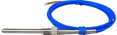
2. Product Introduction
this product is based on the LoRa ® Wireless technology digital temperature sensor, using high-precision sensing elements to collect real-time ambient temperature data, and through the LoRaWAN ® The protocol periodically reports measurements to the application platform. Users can flexibly configure the sampling and reporting cycle through the management platform, and the default setting is to upload data every 15 minutes.
Relying on LoRaWAN ® Standard communication protocol. This product has The advantages of long-distance transmission and low-power operation. It supports access to gateways compatible with various platforms, and is compatible with mainstream IoT platforms such as ThinkLink, ChirpStack, and The Things Network(TTN) to realize remote monitoring and intelligent management of environmental parameters.
It has IP65 level advanced protection, tolerates complex outdoor environment, and is widely used in smart industry, smart buildings, warehousing and logistics, agricultural monitoring and other scenarios to meet the application requirements of all-weather environmental monitoring.
3. Main features
- IP65 protection level
- COV
- Low power LCD display
- Temperature accuracy: ± 0.5 ℃
- Support ThinkLink/ChirpStack/TTN platform docking
- Support US902,AU915,AS923,EU868,EU433,CN470 LoRaWAN standards
4. Parameters
| Parameter | Specification |
|---|---|
| Sensor type | IP65 waterproof sensor (DS18B20 package) |
| Sensor extension cable | 1 meter by default |
| Display | Low-power segment LCD |
| Acquisition interval | 5 seconds |
| Temperature accuracy | ±0.5 ℃ |
| Item | Value |
|---|---|
| § wireless parameters | |
| communication Protocol | standard LoRaWAN ® Agreement |
| regional Standards | CN470/EU433/EU868/AS923/AU915/Us902 |
| transmit power | maximum support 22dBm (can change the parameter) |
| receiving sensitivity | -142dBm(SF=12,BW=125kHz) |
| network access/working mode | OTAA/ABP Class A |
| § protocol/Configuration | |
| test/Trigger Mode | Magnet, 2 seconds trigger heartbeat data,>6 seconds trigger into the network |
| parameter configuration | issuing instructions via NS |
| § physical characteristics | |
| power supply mode | rail switching power supply |
| sleep current | <5uA (25 ℃ at room temperature) |
| emission current | <110mA (22dBm transmit power) |
| working temperature | -40 ° C -125 ° C |
| protection level | IP65 |
| materials & Colors | ABS + PC, White |
| dimensions | 120mm * 72mm * 28mm |
| installation method | wall Hanging |
5. Dimensions and Interfaces
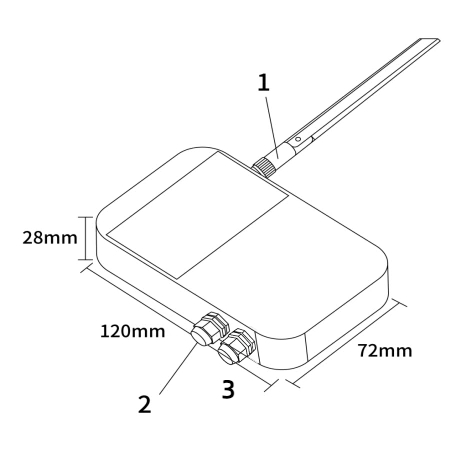
| No. | Interface |
|---|---|
| 1 | LoRa antenna interface |
| 2 | Sensor interface |
| 3 | Power interface |
6. Model List
6.1 Model example
KS538-A1-AS923-N
6.2 Model component breakdown
KS538: product series and RF band.KS53identifies a second-generation IP65 temperature sensor.8identifies the 800 MHz-and-above RF version for EU868, AS923, AU915 and US902.- Other band option:
4identifies the 400 MHz RF version for EU433 and CN470.
-A1: sensor probe and power configuration.Aidentifies a DS18B20 temperature probe.- Other probe option:
Nidentifies a unit supplied without a sensor probe. 1identifies a built-in 10800 mAh battery.- Other power option:
2identifies external DC 5–24 V input without a power output for another device.
-AS923: LoRaWAN regional standard.AS923means that the device supports the LoRaWAN AS923 regional parameters.- Other regional codes are
CN470,EU433,EU868,AU915andUS902;US902denotes the LoRaWAN US915 (902–928 MHz) regional parameters.
-N: antenna configuration.Nidentifies an external antenna with an SMA connector.- Other antenna option:
Sidentifies an internal antenna.
6.3 Complete model meaning
The complete meaning of KS538-A1-AS923-N is:
This is a second-generation IP65 temperature sensor in the 800 MHz-and-above RF class. It includes a DS18B20 temperature probe and a 10800 mAh battery, supports the LoRaWAN AS923 regional standard, and uses an external antenna with an SMA connector.
7. Network Topology
This product is a terminal device that conforms to the standard LoRaWAN protocol, and its normal operation depends on the complete LoRaWAN network support. The network needs to include a LoRaWAN gateway and a network server (NS), where the Gateway can be a brand-compatible gateway, and the NS must have Protocol resolution and device management capabilities.
Supports access to mainstream LoRaWAN Network platforms, including ThinkLink, ChirpStack, and The Things Network (TTN), ensuring flexible deployment and system integration. Users can use ThinkLink IoT platform to configure the object model, implement rich functions such as data parsing, business logic processing, and card view display, and quickly build application systems for actual scenarios.
A typical LoRaWAN network topology is as follows:

8. Working mode
8.1 Periodic Collection and Upload
collect the temperature value every 5 seconds and upload the temperature value according to the set cycle. The Upload cycle can be set by NS delivery.
8.2 COV Upload
COV mode is supported. When the temperature or humidity changes exceed the threshold, a packet of data can be uploaded. The Upload protocol format is the same as the periodic Upload format.
The default COV temperature threshold is 1°C.
8.3 Communication Test
use a magnet to trigger 1S -2s when sticking a two-dimensional code to trigger a packet of upstream measurement data.
8.4 Network access
use a magnet to trigger 6s-8s on the two-dimensional code to trigger a packet of network access data.
9. Installation
9.1 Wall Mount
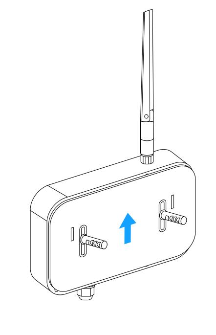
· fix back panel to wall (keep back panel Arrow Up)
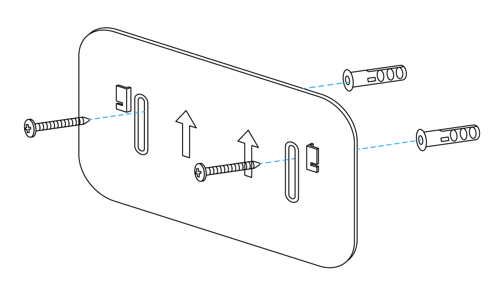
· Tighten the LoRa antenna to the antenna interface
· hitch the temperature sensor to the back plate (slide down after aligning the groove on the back of the sensor with the protrusion on the back of the back plate)
10. Data items and identifiers.
LoRaWAN port number = 11
only one data format is supported. Data is sent periodically according to the set period. When a COV event occurs, one frame of uplink data is triggered.
Example (hex):82 21 05 00a005 DB 0201
| Number | Data Item | Example | Start Address | Length | Description |
|---|---|---|---|---|---|
| 1 | Version number | 0x82 | 0 | 1 byte | Fixed at 0x82 |
| 2 | Control word | 0x21 | 1 | 1 byte | Fixed at 0x21 |
| 3 | Identifier | 0x05 | 2 | 1 byte | Fixed at 0x05 |
| 4 | Device status | 0x00 | 3 | 1 byte | See the bit0 definition below |
| 5 | Temperature | 0x05A0 | 4 | 2 bytes | Unsigned 16-bit little-endian integer; actual temperature = (raw value - 1000) / 10 ℃ |
| 6 | Battery voltage | 0xDB | 6 | 1 byte | Actual value = sample × 1.6 / 254 + 2 V |
| 7 | Reserved bytes | 0x0102 | 7 | 2 bytes | Reserved; do not use for application parsing |
10.1 Device status bit mapping
| Bit | Status item | 0 | 1 |
|---|---|---|---|
| bit0 | Sensor status | Normal | Fault |
11. ThinkLink reference model.
Sign in to ThinkLink.
- search KS53 in Model Management
- add devices according to template MT-KS53
12. Parameter modification
Parameter changes follow PTL-D01 Internet of Things Terminal Application Layer General Protocol V1.5 (see Annex 1).
12.1 Configuration parameter address table
| serial Number | data Item | default Value | start Address | length | description |
|---|---|---|---|---|---|
| 1 | reset | write Only | 9 | 1 byte | write 0x01 |
| 2 | upload cycle | 90 | 40 | 4 bytes | upload cycle, in seconds |
| 3 | acquisition cycle | 5 | 142 | 2 bytes | little Endian mode, in seconds |
| 4 | Temperature COV | 10 | 144 | 1 byte | magnification 0.1, unit ℃ |
13. Contact Us
Website: www.manthink.cn
Email: info@manthink.cn
tel: +86 15810684255