GDO51 Outdoor gateway userguide
1. Product Introduction
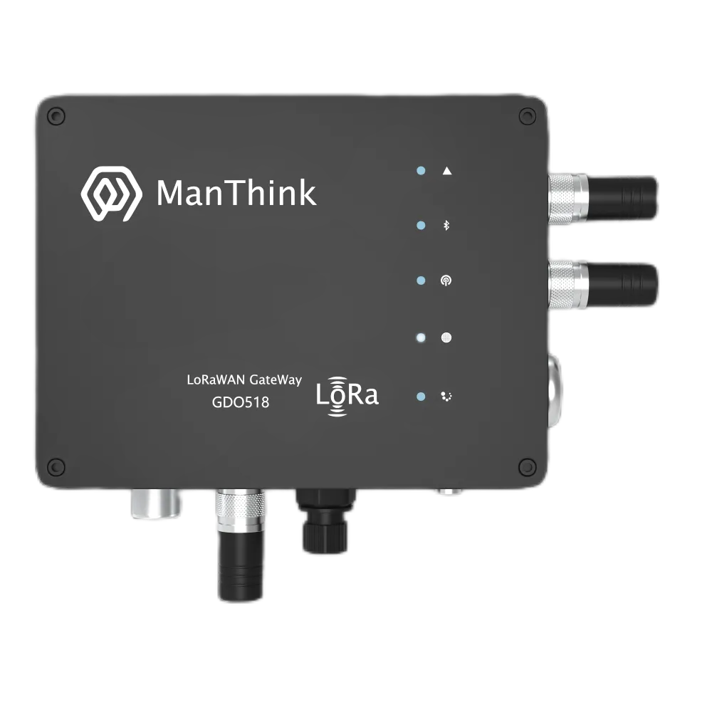
2. Product Description
GDO51 is an outdoor multi-channel high-performance gateway designed by ManThink for LoRaWAN systems. It is not only suitable for the construction of various low-power networks such as cities, factories, and parks, but also suitable for data collection and transmission in harsh environments such as deserts, grasslands, and Gobi. Due to its strong processing power and flexible secondary development environment, it can also play an important role in the next generation of technology waves such as edge computing, AI, and big data.
3. Main features
- Supports built-in TKL (including LoRaWAN NS and IoT platform)
- Supports historical data storage
- Supports Thing Model
- Supports Dashboard
- IP67 protection level
- Support POE, Type-C power supply
- Support 4G, WIFI, Ethernet
- 8 frequency bands (maximum support 16 frequency points)
- maxium support 32(default 16) demodulators capable of processing 32 packets simultaneously
(16 × SF5-SF12 LoRa® demodulators; 16 × SF5-SF10 LoRa® demodulators)
- maxium 130 (default 65) channels (each channel configuration includes distinct SF, BW, and frequency points; BW = 125 kHz, totaling 65 channels)
- Receiver sensitivity: -141 dBm (SF = 12, BW = 125 kHz)
- Maximum RF transmit power: 22 dBm
- Support US902, AU915, AS923, EU868, EU433, CN470 LoRaWAN standard
- External SIM card and debugging interface for easy maintenance and repair
- Seamless connection to LoRaWAN netservers such as TTN, ChirpStack, and Basicstaion
- Supports remote maintenance and upgrades
- Web-based visualization and friendly configuration
4. Electrical parameters
| Category | Parameter | Specification |
|---|---|---|
| § Compute and storage | ||
| SOC | LS1012A 64-bit ARM Cortex-A53 800MHz 2W | |
| Memory type/rate | Support DDR3L 1066 MHz | |
| Memory capacity | Memory:512MB | |
| Storage | ≥ 16 GB eMMC | |
| § Software | ||
| Platform | Built-in NS and IoT platform (with integrated TKL) | |
| Protocol/platform support | ThinkLink, ChirpStack, TTN, Basic Station, and GWMP protocols | |
| Databases | PostgreSQL and Redis | |
| Historical data | historical data storage | |
| Leaf mode | Leaf mode | |
| Thing Model | Thing Model | |
| Application data parsing | application data parsing | |
| Visualization | Dashboard | |
| § LoRa | ||
| Operating frequency bands | CN470: 470–510 MHz EU868: 863–870 MHz EU433: 433–434 MHz AS923: 920–928 MHz US902: 902–928 MHz AU915: 915–928 MHz | |
| Communication rate | 292bps to 15.625kbps | |
| Spreading factors | supports SF5 to SF12 | |
| Transmit power | 22dBm (Max) | |
| Receiver sensitivity | -141 dBm (SF = 12, BW = 125 kHz) | |
| Antenna type | Omnidirectional | |
| Frequency points | 8 (maximum 16)(BW = 125 kHz) | |
| Demodulators | 16 (maximum 32) | |
| Concurrent packets | 16 (maximum 32) packets simultaneously | |
| Demodulator composition | 8(maximum 16) × SF5-SF12 LoRa® demodulators; 8 (maximum 16) × SF5-SF10 LoRa® demodulators | |
| Channels | 65(maximum 130) | |
| Channel definition/note | each channel is defined by a unique combination of SF, BW, and frequency point; BW = 125 kHz, totaling 65 channels | |
| Operating mode | Half-duplex | |
| Single-channel bandwidth | 125KHz or higher | |
| § Network and backhaul | ||
| Ethernet | 1000M/100M | |
| 4G uplink | The gateway uses CAT1 module for 4G uplink by default | |
| LTE-FDD bands | B1/3/5/8 | |
| LTE-TDD bands | B34/38/39/40/41 | |
| 4G deployment note | If the operator's frequency band in the planned deployment area is not within the above, please contact ManThink technical personnel to replace the appropriate 4G module. | |
| § Ports and timing | ||
| USB Type-C configuration | USB-TypeC | |
| Ethernet configuration | Ethernet | |
| Wi-Fi configuration | WiFi | |
| SIM card interface | nano SIM external interface (no need to open the cover for replacement) | |
| Timing | GPS | |
| § Power | ||
| Power supply | POE(48V) | |
| Power consumption | 5W | |
| § Environment and enclosure | ||
| Operating temperature | -40℃~70℃ | |
| Operating humidity | 0%~95%RH | |
| Water and dust resistance | IP67 | |
| Weight | 1.2KG | |
| Dimensions | 164x124x50mm | |
| Installation method | Pole or wall mounting |
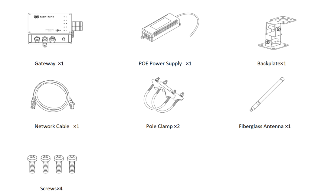
5. Accessories List
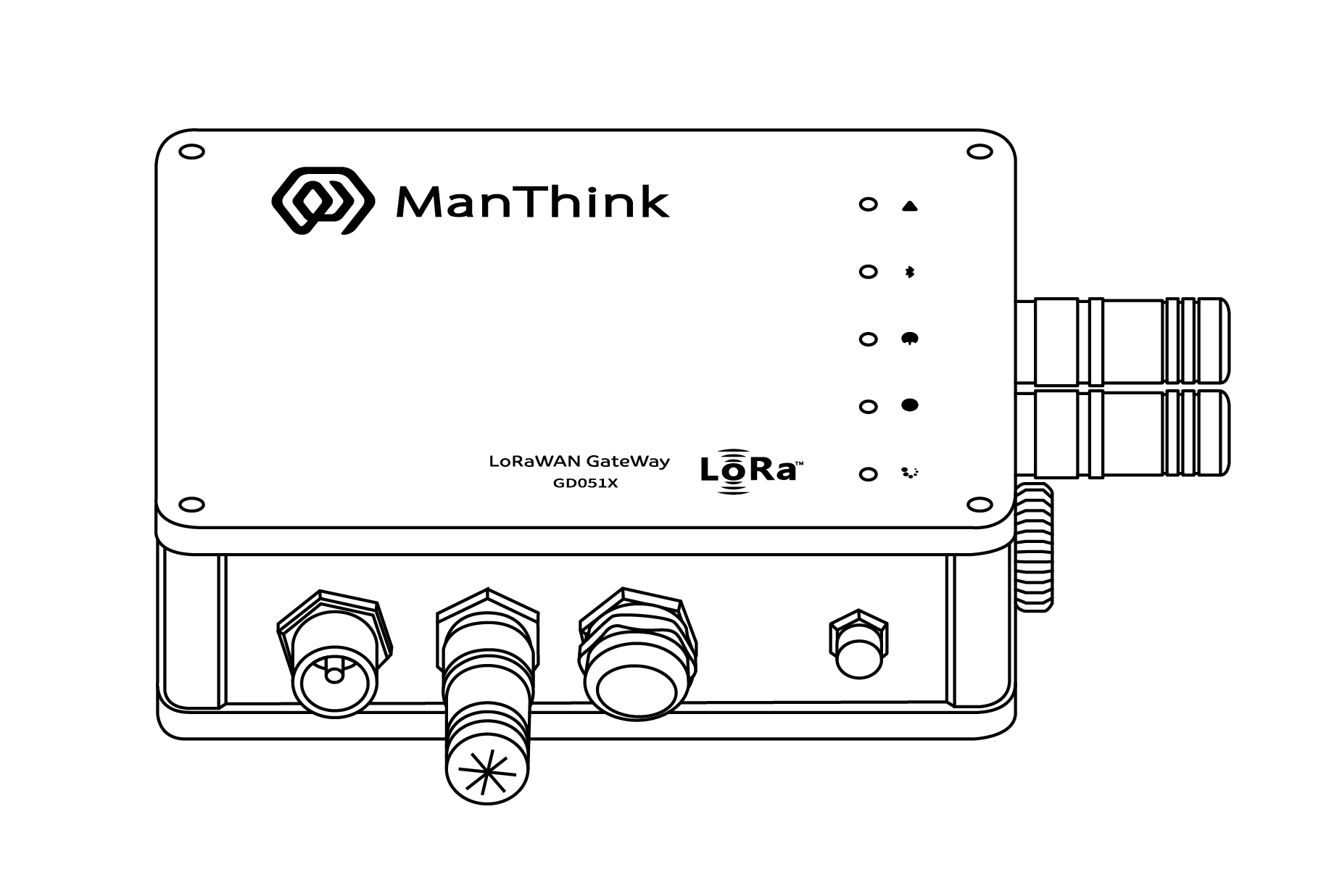
6. Gateway Body
7. Product Dimensions
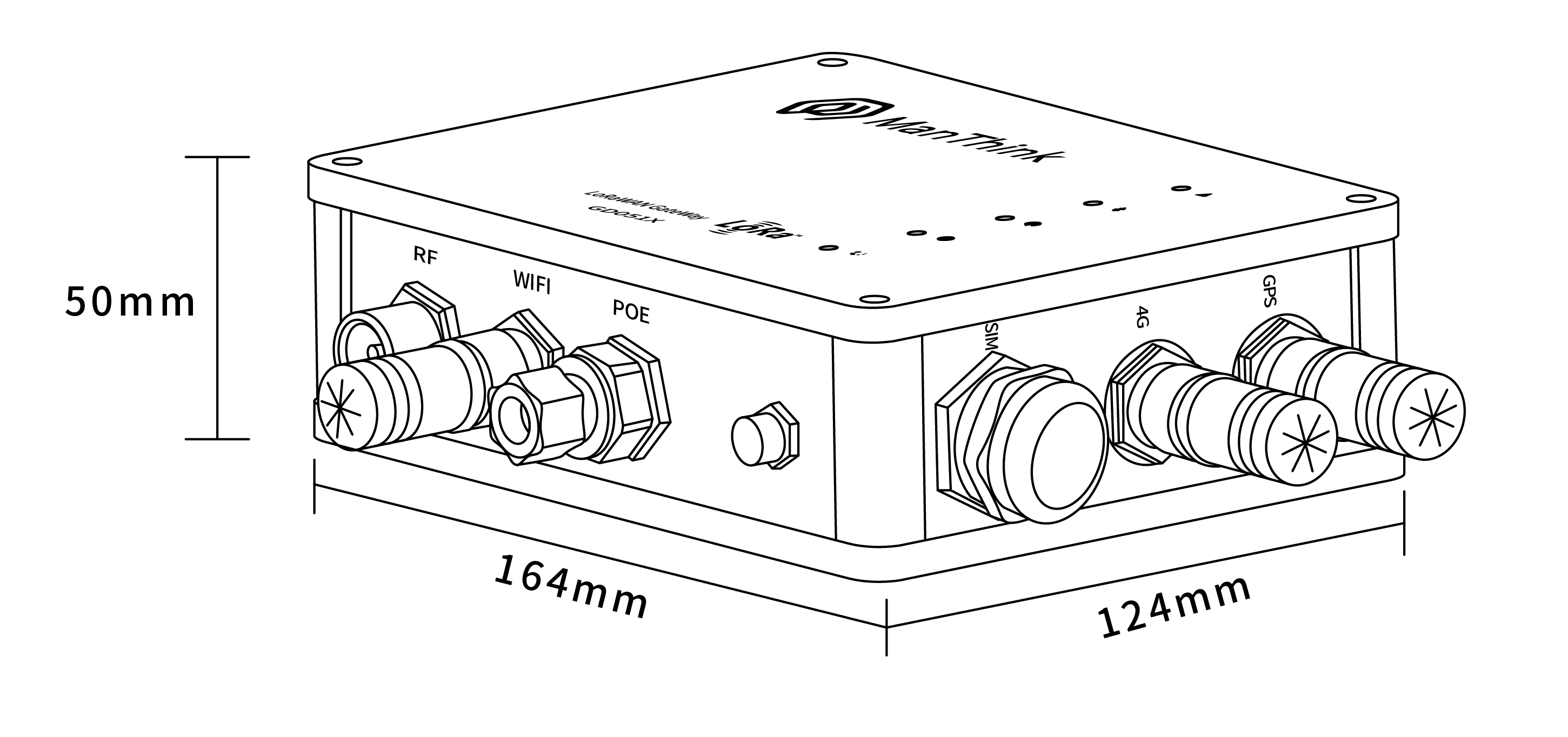
8. Interface Description
| Interface Name | Description |
|---|---|
| RF | LoRa Antenna Interface |
| WIFI | WIFI Antenna Interface |
| POE | POE Power Interface |
| SIM | SIM Card Slot |
| 4G | 4G Antenna Interface |
| GPS | GPS Antenna Interface |
9. Indicator Light Description
| Indicator | Color / network | Light states and meanings |
|---|---|---|
Running indicator  | — | Steady on: The system is starting. Off: Basic system startup is complete and application processes are starting. Flashing at 1 Hz: The system is running normally. |
Network indicator  | Blue/wired network Green/4G network | Blue, flashing at 1 Hz: The wired network connection is normal. Blue, flashing every 500 ms: The wired network connection is abnormal. Blue, flashing rapidly: Network configuration is in progress. Green, off: No 4G module is installed. Green, steady on: A 4G module is installed, but no SIM card is inserted. Green, flashing irregularly: Data is being exchanged over the 4G network. |
LoRa data transceiver indicator  | Green Blue | Green, flashing: A LoRa data packet is being transmitted. Blue, flashing: A LoRa data packet is being received. |
LAN status light  | Red Blue | Red: System control status. Blue: Wi-Fi connection status. |
Fault indicator  | — | Flashing rapidly: The system is in the second startup phase. Off: No system fault is present. Flashing: The system has detected a fault. |
10. Product Model
10.1 Model example
GDO518-AG-AS923-N-2
10.2 Model component breakdown
GDO518: product series and RF band.GDO51identifies a fifth-generation outdoor LoRaWAN gateway.8identifies the 800 MHz-and-above RF version for EU868, AS923, AU915 and US902.- Other band option:
4identifies the 400 MHz RF version for EU433 and CN470.
-AG: LoRa architecture and 4G configuration.Aidentifies one LoRa antenna, 8 frequency points, 65 channels and half-duplex operation.- Other LoRa architecture option:
Didentifies two LoRa antennas, 16 frequency points, 130 channels and full-duplex operation. Gidentifies an integrated 4G module.- Other 4G option:
Nidentifies a configuration without a 4G module.
-AS923: LoRaWAN regional standard.AS923means that the gateway supports the LoRaWAN AS923 regional parameters.- Other regional codes are
CN470,EU433,EU868,AU915andUS902;US902denotes the LoRaWAN US915 (902–928 MHz) regional parameters.
-N: default version.Nidentifies the default version.- Other values are reserved for customized or special versions.
-2: LoRa concentrator chipset.2identifies the Semtech SX1302.- Other chipset option:
1identifies the Semtech SX1301.
10.3 Complete model meaning
The complete meaning of GDO518-AG-AS923-N-2 is:
This is a fifth-generation outdoor LoRaWAN gateway in the 800 MHz-and-above RF class. It uses one LoRa antenna, 8 frequency points, 65 channels and half-duplex operation, includes a 4G module, supports the LoRaWAN AS923 regional standard, uses the default version code N, and is equipped with a Semtech SX1302 concentrator.
11. Gateway Installation
Note: It is not necessary to disassemble the Gateway shell during installation.
12. Installation Direction
Note: The front view of the product is shown in the picture above. GPS and 4G antenna interface to the right, WiFi antenna interface down. During the installation process, please ensure that the product orientation is consistent with the above figure for correct installation.
13. Backplane Installation
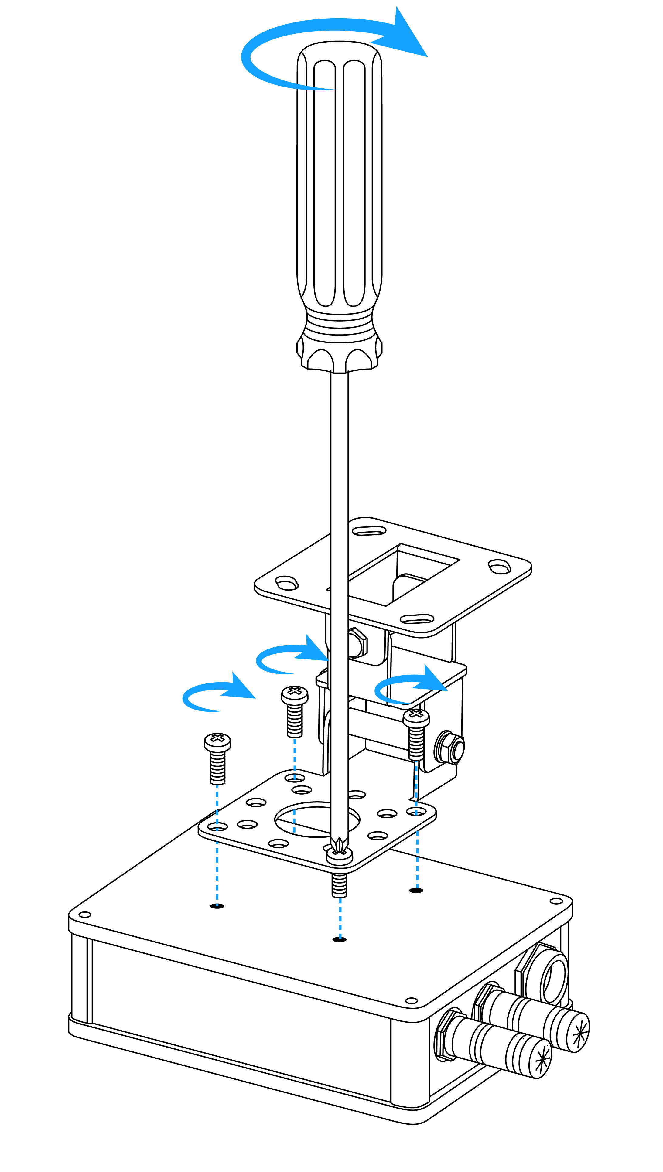
- Flip the gateway to the direction shown in the figure and confirm that the backplane is tightly connected to the Gateway.
- Align the screw with the screw hole and use a screwdriver to turn it clockwise until the screw cannot turn.
14. Network cable installation
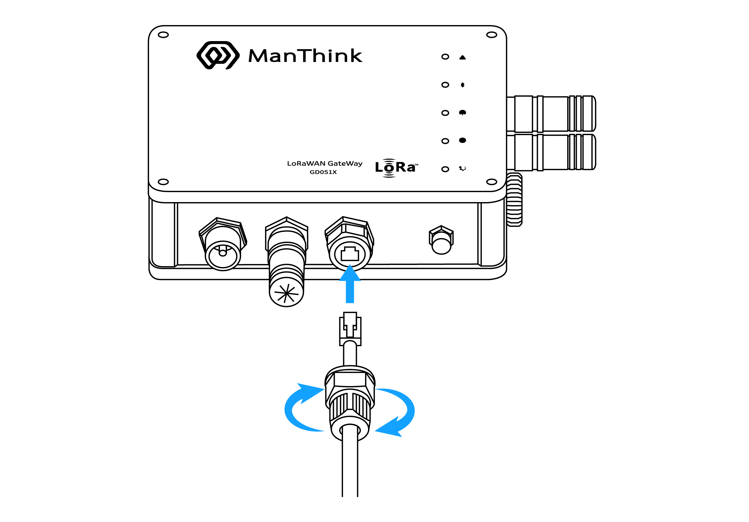
- Thread the waterproof plug into the network cable from right to left in the following order, and assemble parts 1, 2, 3 and 4 tightly
- Insert one end of the network cable crystal head into the Gateway POE interface
- Move the assembled waterproof plug part to the direction of the Crystal Head, and screw it on the POE interface to ensure that the assembled waterproof plug is tightly connected with the POE interface.

15. SIM card installation
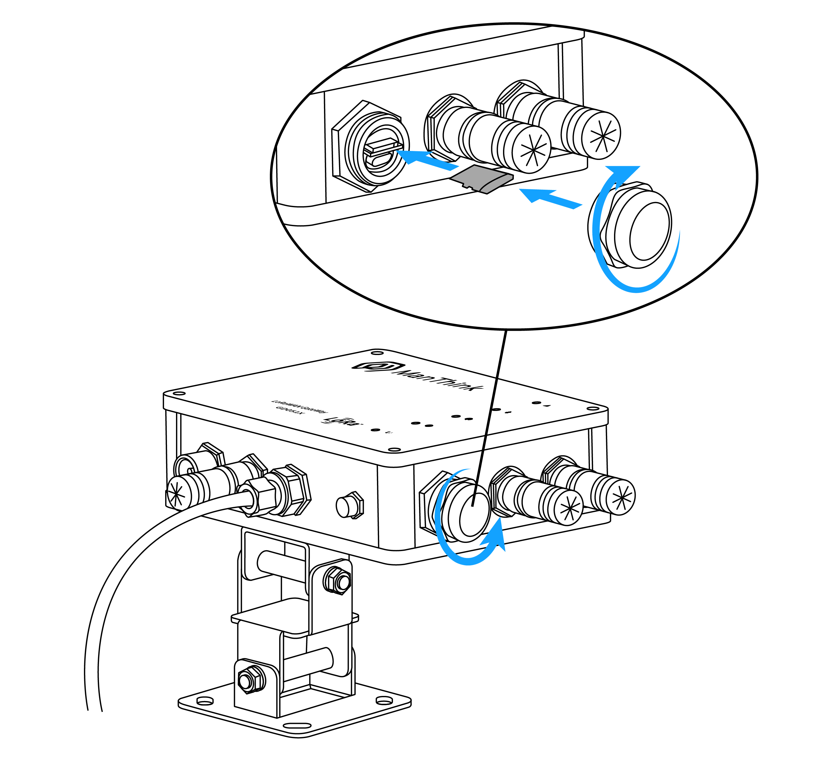
- Unscrewing the waterproof cover on the SIM interface
- Keep the SIM card metal patch position towards the TYPE-C interface
- Insert the SIM card into the card slot and tighten the waterproof cover.
16. Power connection
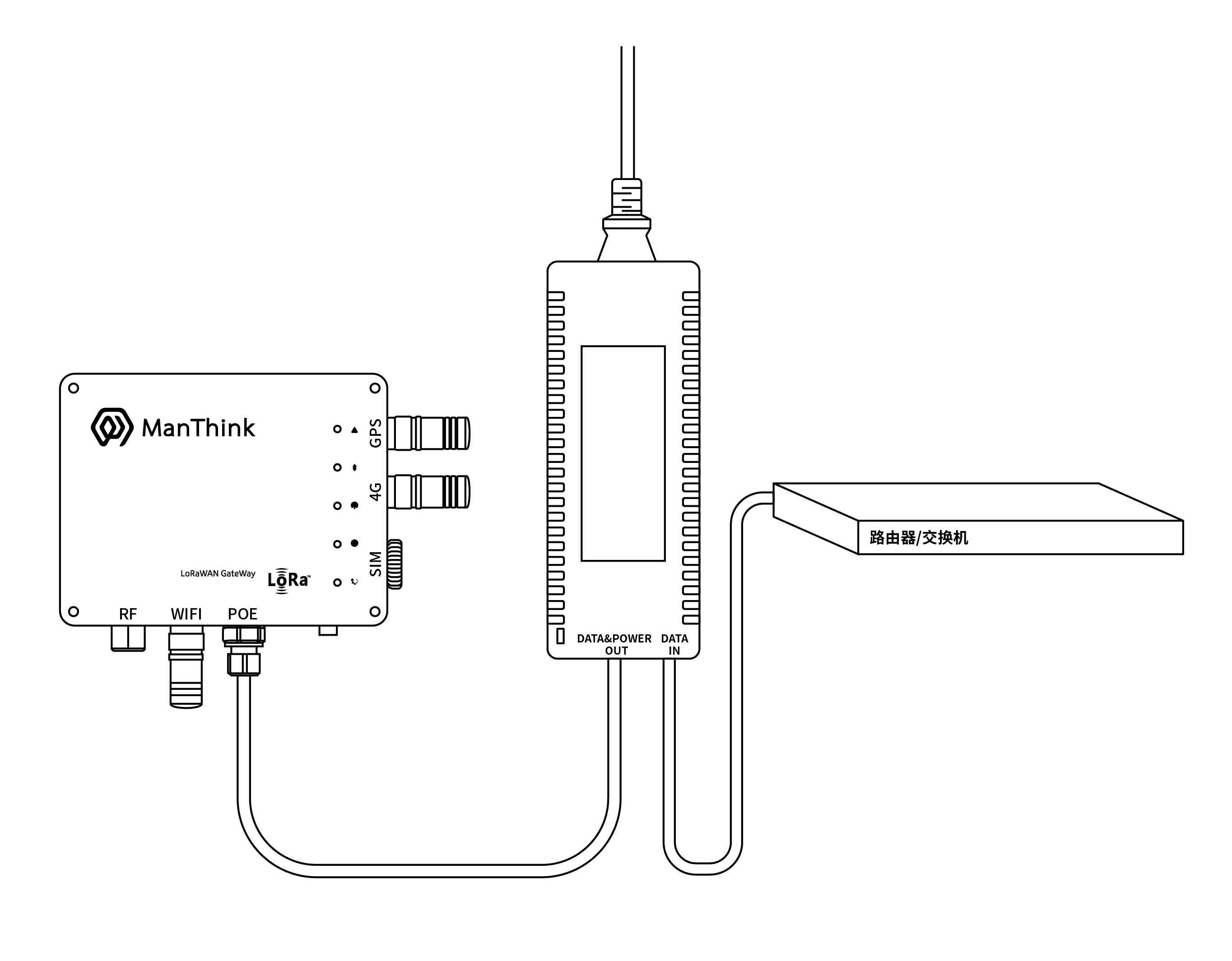
- OUT port connection gateway POE interface (power supply)
- The IN port is connected to a switch or router (network supply). If there is 4G, there is no need to connect the IN interface.
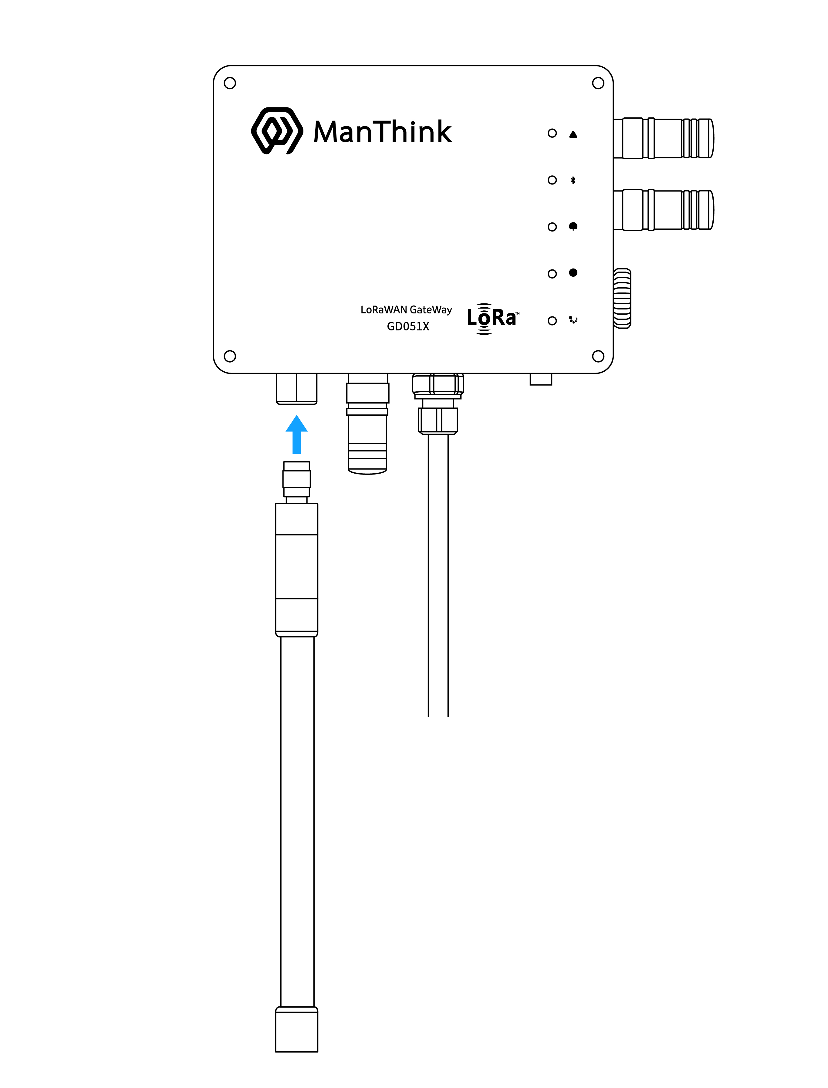
17. FRP antenna installation
- [x] Connect the LoRa antenna to the Gateway RF interface
Note: This step is required for the optional lora antenna.
18. Gateway fixed
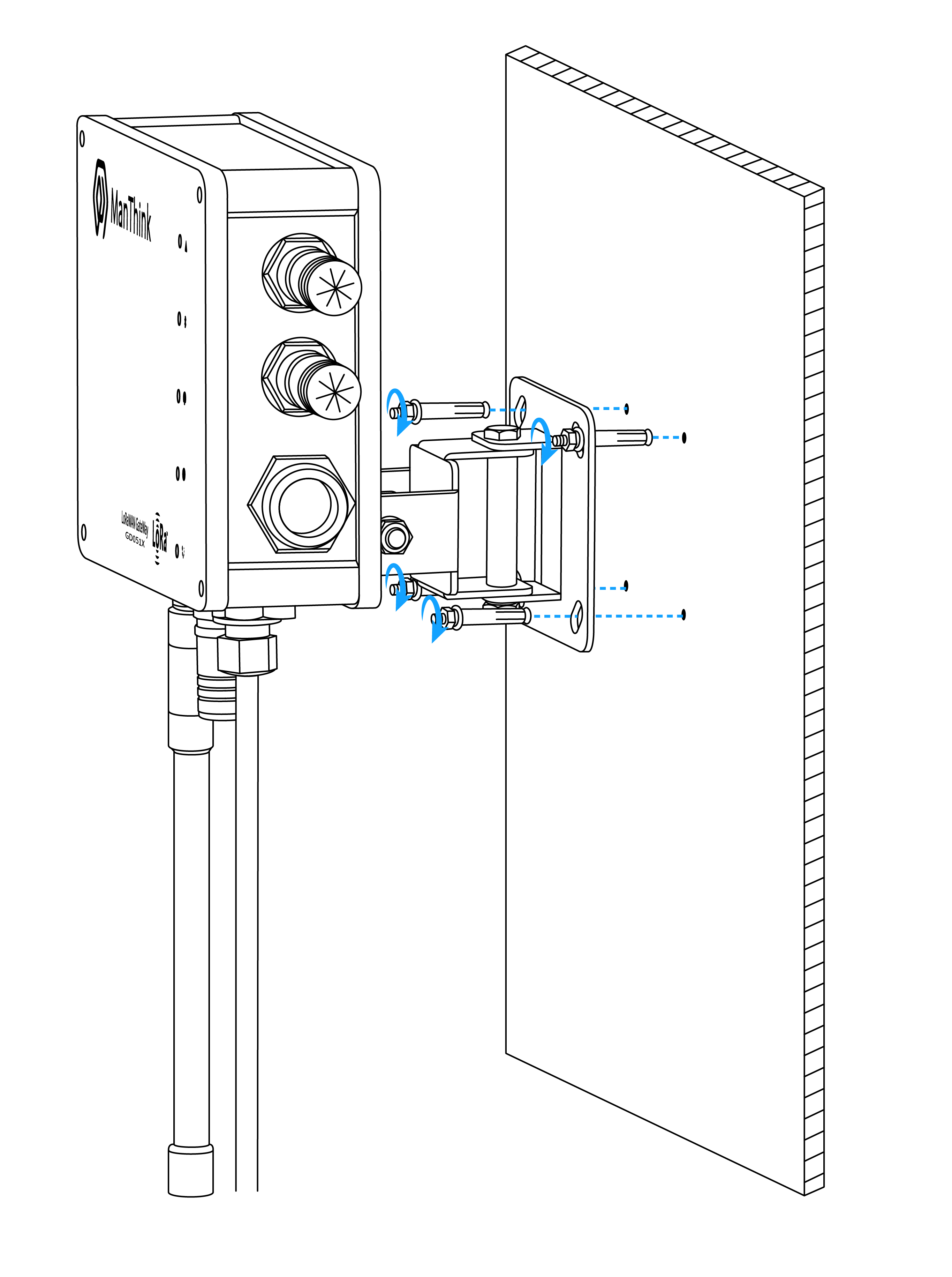
18.1 Wall-mounted fixed
- Install with the Gateway face up (Figure 1)
- Four holes corresponding to the holes of the back plate bracket are made in the wall, and then the expansion bolts are driven in (the positions of the four holes of the back plate bracket can be marked on the wall first)
- Pass the expansion screw through the back bracket and screw in the expansion screw with a tool.
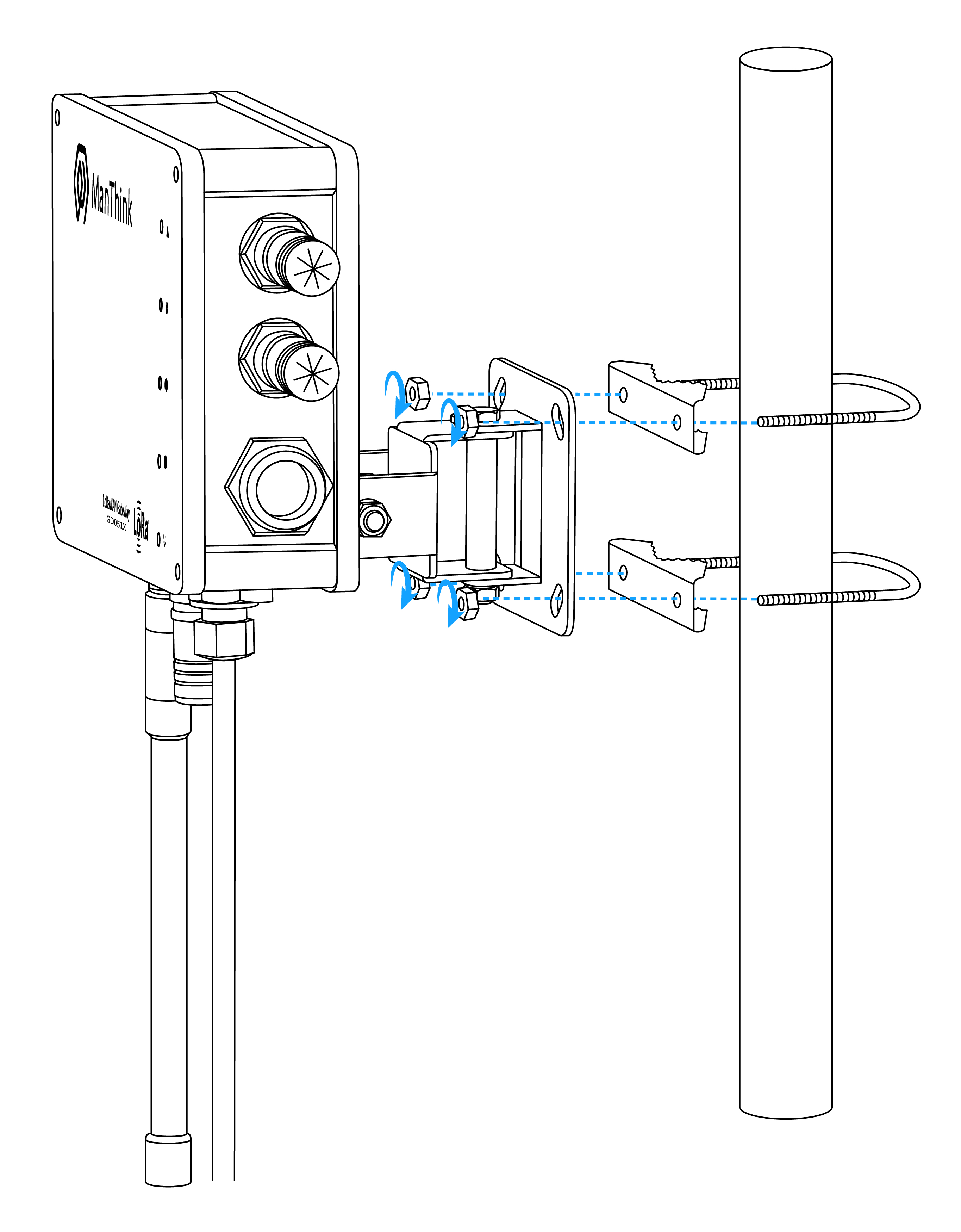
18.2 Holding Rod fixing
- Install with the Gateway face up (Figure 2)
- Confirm that the pole diameter is between 30mm-52mm
- Combine the holding Rod clamps according to the position shown in the figure, and tighten the screws.
19. Waterproof protection
- Use insulating tape or waterproof material to wrap and seal the connection to ensure that it is not penetrated by moisture and moisture.
- Pay special attention to areas where moisture can easily enter, such as outdoor installations or areas exposed to rain or high humidity.
- The insulating tape is tightly wrapped around the connection, completely covered, and forms a waterproof barrier.
- Check the waterproof condition regularly, and re-coat or replace the insulating tape as needed to maintain effective protection.
- Ensure that all connections and cables are properly sealed and protected to prevent moisture damage and maintain the integrity of the installation.
20. Gateway waterproof
- Ensure all cable entry points and connectors on the Gateway are properly sealed following the installation steps
- Pay particular attention to areas where moisture may enter, such as cable connections, antenna interfaces, and power input ports.
- Apply a layer of waterproof material around the cable entry point and connector, completely covering to prevent moisture penetration.
- Check the waterproof condition regularly, and re-coat or replace the waterproof material as needed to maintain effective protection.
21. POE adapter waterproof installation
- Cose a suitable location to install the POE Adapter, making sure it is away from direct water sources or areas that may splash water.
- Make sure that the POE Adapter is installed vertically with the connection port down to prevent water from entering.
- Use a waterproof material, such as insulating tape or waterproof casing, to cover and seal the connection of the POE Adapter.
- Pay attention to the entry points of the cables and make sure they are properly sealed to prevent water from entering.
- Check waterproofing measures regularly and re-coat or replace any damaged or aged materials.
Please note that waterproofing requirements may vary depending on the specific environment and installation conditions. To ensure effective waterproofing, follow best practices and consult a professional if needed.
22. Gateway Configuration
gwTool7 Gateway Administrator Manual
23. Using ThinkLink
\ThinkLink User Guide
24. Connecting to Chirp Stack
Connect to ChirpStack with Basic Station (gwTool7)
25. Connecting to TTN
Connect to TTN with Basic Station (gwTool7)
Legacy WebServer (old batches only)
Old GDO51 batches use the legacy WebServer. Connect to the gateway Wi-Fi and open http://192.158.1.1; if the login page displays Welcome to Your WebConfigure, use these historical guides:
26. Contact Us
Website: www.manthink.cn
Email: info@manthink.cn
Tel: +86-15810684257