KS31 LoRaWAN Analog Input Collector specificationV2.0
Product Introduction
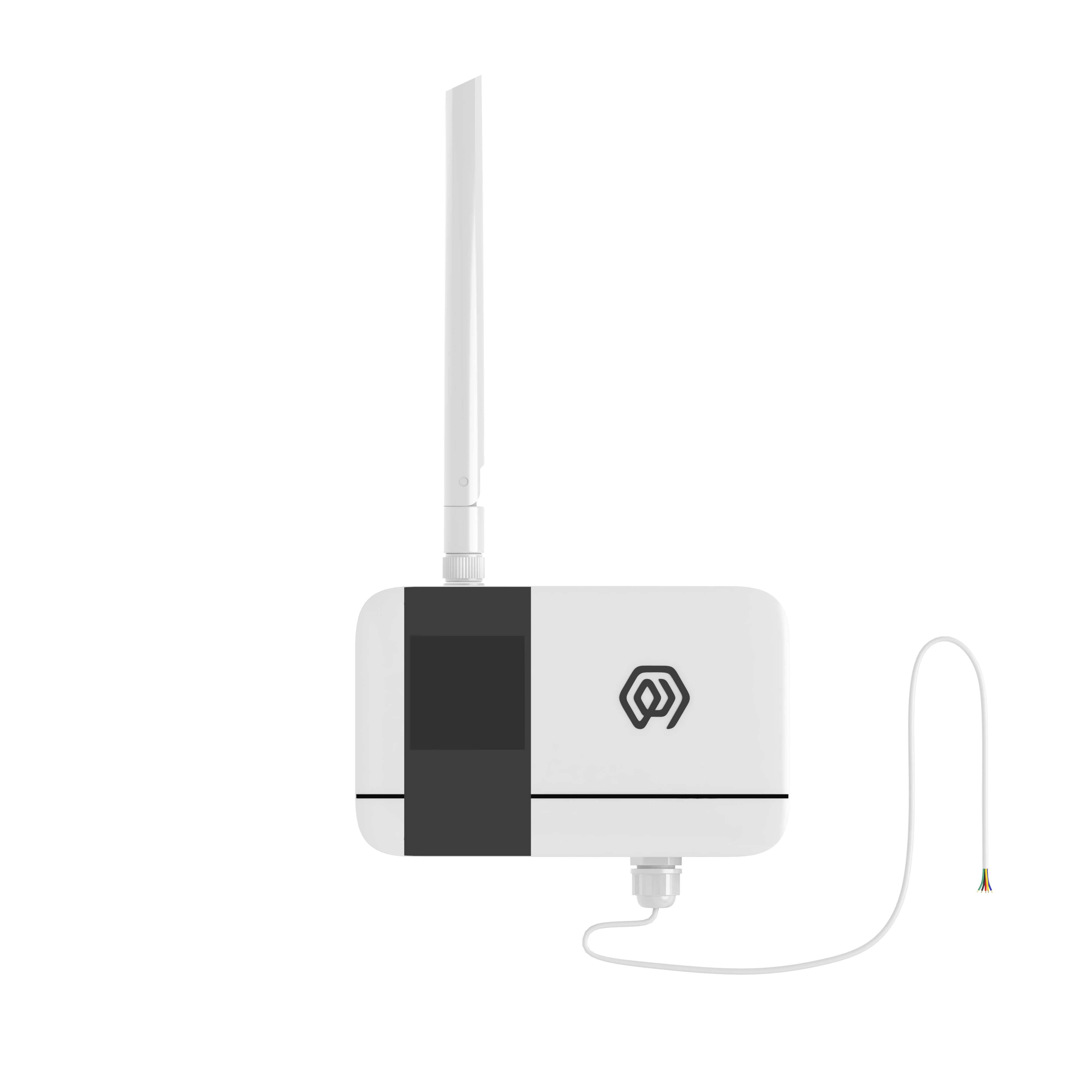
Product Description
KS31 is a LoRaWAN-based The AI collector for communication provides 4-20mA and 0-10v interfaces, which can easily connect devices supporting the above two interfaces.
KS31 based on LoRa ® Wireless technology, supports standard LoRaWAN ® Networking communication has the characteristics of long communication distance and low power consumption. The product has 4 built-in 2700 mA-hour large-capacity lithium battery, which can last for more than 6 years.
Product support with ManThink/third-party LoRaWAN ® The gateway is combined with the ThinkLink/Chirp stack/TTN third-party IoT platform to realize the monitoring and management of 4-20mA and 0-10v interface switches.
KS31 has a high protection level of IP65, adapt to the harsh outdoor environment, and can be widely used in the management needs of smart industries, smart buildings and other scenarios.
Main Features
- IP65 protection rating .
- Support 4-20mA, 0-10V interface.
- Battery powered, 10800mA high performance lithium battery, battery life up to 6 years.
- Support ThinkLink/ChirpStack/TTN platform docking.
- Support US902,AU915,AS923,EU868,EU433,CN470 LoRaWAN standard.
Specifications
Performance Parameters
| Item | Value |
|---|---|
| § Interface | |
| connect type | PG7 |
| Wiring quantity | 5 (Including GND wire) |
| Number of grounding wires | 1 |
| display | none |
| § Wireless Parameters | |
| Protocol | Standard LoRaWAN ® Agreement |
| Regional Standards | CN470/EU433/EU868/AS923/AU915/Us902 |
| Transmit Power | Maximum Support 22dBm ( can be changed) |
| Receiving Sensitivity | -142dBm(SF=12,BW=125kHz) |
| Working mode | OTAA/ABP Class A |
| § Configuration | |
| Test /Trigger mode | The magnet, 2 seconds trigger heartbeat data 6 seconds trigger into the network |
| Configuration | By NS issue instruction |
| § Physical Characteristics | |
| power supply mode | 4*2700mAh ER14505 lithium battery |
| Sleep current | < 3uA (25°C at room temperature) |
| Emission current | < 110mA (22dBm transmit power) |
| Battery life | 6 years (15-minute reporting cycle, 25 °C at room temperature) |
| Working Temperature | -40°C ~85°C |
| Relative humidity | ≤95% (no condensation) |
| Protection level | IP65 |
| Material & Color | ABS + PC, White |
| Dimensions | 120mm * 72mm * 28mm |
| Installation method | Wall Hanging |
Dimensions and Interfaces
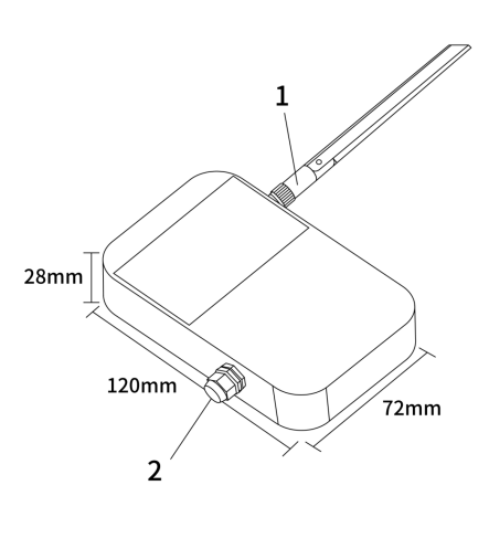
| Serial Number | Iinterface Description | Specific details |
|---|---|---|
| 1 | LoRa Antenna interface | Inner hole outer screw, according to different LoRaWAN standard match |
| 2 | Wiring Port | PG7 waterproof connector, 1 GND,4 leads, 5 leads in total |
2.3 Model List
Model example
KS318-A1-AS923-N
Model component breakdown
KS318: product series and RF band.KS31identifies a second-generation IP65 analog input acquisition module.8identifies the 800 MHz-and-above RF version for EU868, AS923, AU915 and US902.- Other band option:
4identifies the 400 MHz RF version for EU433 and CN470.
-A1: acquisition interface and power configuration.Aidentifies a 4–20 mA analog input.- Other interface option:
Bidentifies a 0–10 V analog input. 1identifies a built-in 10800 mAh battery.- Other power option:
2identifies external DC 5–24 V input.
-AS923: LoRaWAN regional standard.AS923means that the device supports the LoRaWAN AS923 regional parameters.- Other regional codes are
CN470,EU433,EU868,AU915andUS902;US902denotes the LoRaWAN US915 (902–928 MHz) regional parameters.
-N: default version.Nidentifies the default version.- Other values are reserved for customized or special versions.
Complete model meaning
The complete meaning of KS318-A1-AS923-N is:
This is a second-generation IP65 analog input acquisition module in the 800 MHz-and-above RF class. It provides a 4–20 mA analog input, includes a 10800 mAh battery, supports the LoRaWAN AS923 regional standard, and uses the default final version code N.
Instructions For Use
Network Topology
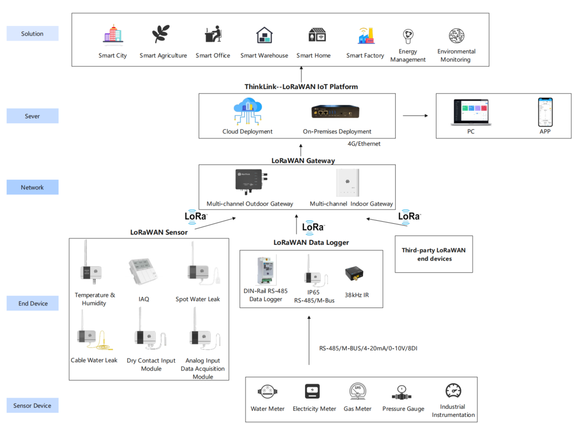
KS31 is a standard LoRaWAN device, KS31 normal operation requires LoRaWAN network support. You can use the LoRaWAN gateway of ManThink or a third-party LoRaWAN gateway with the support of LoRaWAN NS.
KS31 supports access to standard LoRaWAN networks such as ThinkLink, Chirp stack, and TTN. You can use the ThinkLink configuration model to implement business functions, card view presentation, and other business logic.
The LoRaWAN network topology is as follows:
Working Mode
Periodic Acquisition and Heartbeat
- [x] The KS31 has 4 AI interfaces that perform periodic sampling and transmit data periodically.
- [x] The KS31 allows setting a COV (Change of Value) threshold. When the sampled data from an AI interface exceeds this threshold, it triggers an uplink data packet.
- [x] The protocol format for triggered uploads and periodic heartbeats is the same.
Communication Test
Use a magnet to stick the position of QR code on KS31 to trigger 2s-4S, which can trigger a packet of upstream measurement data.
Join
Use a magnet to stick the position of QR code on KS31 to trigger 6s-8s, which can trigger a packet of join.
Installation
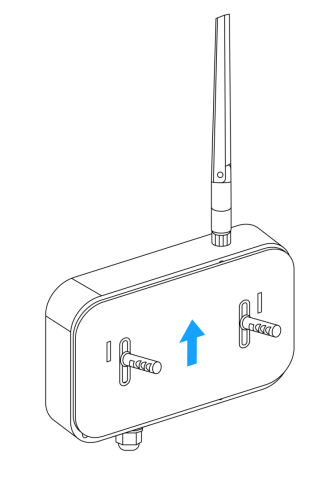
- [x] Use the drill to fix the back plate to the Wall (keep the back plate Arrow Up)
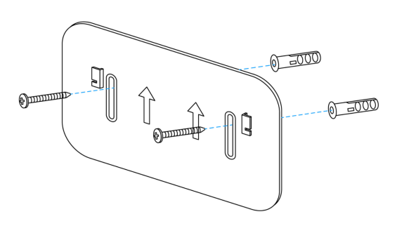
- [x] Hatch the product on the back plate (slide down after aligning the groove on the back of the sensor with the convex part of the back plate)
communication Protocol
According to the Standard
Reference: PTL-D01 ManThink Technology IoT Terminal Application Layer General Protocol V1.5
Note: The 0–10 V and 4–20 mA models use different identifiers; all other fields have the same layout.
Data items and identifiers for 0-10V Interfaces
LoRaWAN port 11; version 0x82; control word 0x25; identifier 0x17.
Example frame:
82 25 17 00 D4 15 01 00 D0 16 00 00 D0 16 01 00 D0 16 01 00 FE| Number | Data Item | Example | Start Address | Length | Description |
|---|---|---|---|---|---|
| 1 | Version | 0x82 | 0 | 1 byte | Fixed at 0x82 |
| 2 | Control word | 0x25 | 1 | 1 byte | Fixed at 0x25 |
| 3 | Identifier | 0x17 | 2 | 1 byte | Fixed at 0x17 for the 0–10 V model |
| 4 | Device status | 0x00 | 3 | 1 byte | 0x00: normal; 0x01: communication fault |
| 5 | Port 1 sample | D4 15 01 00 → 0x000115D4 | 4 | 4 bytes | Unsigned 32-bit little-endian integer; actual value = sample × 11 / 64000.00 V |
| 6 | Port 2 sample | D0 16 00 00 → 0x000016D0 | 8 | 4 bytes | Unsigned 32-bit little-endian integer; actual value = sample × 11 / 64000.00 V |
| 7 | Port 3 sample | D0 16 01 00 → 0x000116D0 | 12 | 4 bytes | Unsigned 32-bit little-endian integer; actual value = sample × 11 / 64000.00 V |
| 8 | Port 4 sample | D0 16 01 00 → 0x000116D0 | 16 | 4 bytes | Unsigned 32-bit little-endian integer; actual value = sample × 11 / 64000.00 V |
| 9 | Battery voltage | 0xFE | 20 | 1 byte | Actual value = sample × 1.6 / 254 + 2 V |
Data items and identifiers for the 4-20mA interface
LoRaWAN port 11; version 0x82; control word 0x25; identifier 0x18.
Example frame:
82 25 18 00 D4 15 01 00 D0 16 00 00 D0 16 01 00 D0 16 01 00 FE| Number | Data Item | Example | Start Address | Length | Description |
|---|---|---|---|---|---|
| 1 | Version | 0x82 | 0 | 1 byte | Fixed at 0x82 |
| 2 | Control word | 0x25 | 1 | 1 byte | Fixed at 0x25 |
| 3 | Identifier | 0x18 | 2 | 1 byte | Fixed at 0x18 for the 4–20 mA model |
| 4 | Device status | 0x00 | 3 | 1 byte | 0x00: normal; 0x01: communication fault |
| 5 | Port 1 sample | D4 15 01 00 → 0x000115D4 | 4 | 4 bytes | Unsigned 32-bit little-endian integer; actual value = sample × 10 / 64000.00 mA |
| 6 | Port 2 sample | D0 16 00 00 → 0x000016D0 | 8 | 4 bytes | Unsigned 32-bit little-endian integer; actual value = sample × 10 / 64000.00 mA |
| 7 | Port 3 sample | D0 16 01 00 → 0x000116D0 | 12 | 4 bytes | Unsigned 32-bit little-endian integer; actual value = sample × 10 / 64000.00 mA |
| 8 | Port 4 sample | D0 16 01 00 → 0x000116D0 | 16 | 4 bytes | Unsigned 32-bit little-endian integer; actual value = sample × 10 / 64000.00 mA |
| 9 | Battery voltage | 0xFE | 20 | 1 byte | Actual value = sample × 1.6 / 254 + 2 V |
ThinkLink Reference Model
Sign in to ThinkLink, search for KS31 in the model menu, and add the device with the KS31 template.
Parameter Modification
Parameter changes follow PTL-D01 ManThink Technology IoT Terminal Application Layer General Protocol V1.5.
Configuration Parameter Address Table
| Number | Data Item | Default Value | Start Address | Length | Description |
|---|---|---|---|---|---|
| 1 | Reset | Write-only | 9 | 1 byte | Write 0x01 |
| 2 | Upload period | 900 | 40 | 4 bytes | Little-endian, in seconds |
| 3 | COV enable mask | 0x0F | 150 | 1 byte | bit0–bit3 correspond to AI channels 1–4; 0: disable COV, 1: enable COV |
| 4 | System reserved | — | 151 | 1 byte | Reserved |
| 5 | Sampling period | 5 | 152 | 2 bytes | Little-endian, in seconds |
| 6 | Channel 1 COV | — | 154 | 4 bytes | Unsigned 32-bit little-endian integer; 4–20 mA threshold = COV × 10 / 64000.00 mA; 0–10 V threshold = COV × 11 / 64000.00 V |
| 7 | Channel 2 COV | — | 158 | 4 bytes | Unsigned 32-bit little-endian integer; use the channel 1 conversion |
| 8 | Channel 3 COV | — | 162 | 4 bytes | Unsigned 32-bit little-endian integer; use the channel 1 conversion |
| 9 | Channel 4 COV | — | 166 | 4 bytes | Unsigned 32-bit little-endian integer; use the channel 1 conversion |
Contact Us
Website: www.manthink.cn
Email: info@manthink.cn
Tel: +86-15810684257
Manual Downloads
These are permanent download URLs and will remain unchanged when the manuals are updated.