Userguide of EB compiler SDK
1. Overview
1.1 Core Concepts
The EB Compiler SDK is an event-driven framework for data collection and transmission. Its core logic consists of:
- Event-driven architecture: All operations are triggered and executed based on events.
- Periodic execution: Both query events and uplink events are cyclical.
- Data stream processing: Sub-device data is acquired through query events, processed, and then transmitted to the cloud via uplink events.
1.2 Event Types
- Query Event: Periodically sends commands to sub-devices to retrieve data.
- UpAfterQueryEvent: Uploads data directly to the cloud immediately after retrieval without additional processing.
- LoraUp Event: Periodically transmits processed data to the cloud via LoRaWAN.
1.3 Compilation Method
1.3.1 Environment Setup
- First, install Node.js on your system (the LTS version is recommended).
- Run the following command in the terminal to install ts-node globally:
npm install -g ts-node1.3.2 Compilation
Execute npm install to install dependencies before proceeding.
Example script execution on Windows:
ts-node .\project\test\test.tsEnsure your TypeScript environment is properly configured and verify the file path before execution.
1.4 Firmware Download
1.4.1 Multi-BIN Upgrade Instructions
EB's upgrade adopts a multi-BIN approach. The compiled binary file is segmented into multiple packages and sequentially delivered to the device according to the frame number. The compiled OBIN file already contains internal packetization information. The upgrade process involves sending multiple data packets one by one to the device, which will then verify the integrity and validity of the upgrade packets. Upon successful verification, the packets are written to the device's code area, completing the upgrade functionality.
When the obin file is read as text, its content is a JSON-formatted file as shown below. The valid upgrade packets are found in bin_dic. The packet sequence is indicated by index, where index=0 represents the first data packet. Other information pertains to configurations used during upgrades via ThinkLink, UART, or SW modes.
During compilation, a unique version number must be specified. After the upgrade is completed, this version number can be retrieved to determine whether the upgrade was successful.
{
  "otaFile": {
    "bin_dic": {
      "0": {
        "index": 0,
        "buffer": "AgADAGQDWQQAAAA=",
        "bufferstring": "02 00 03 00 64 03 59 04 00 00 00"
      },
      "1": {
        "index": 1,
        "buffer": "CAAAAgAAADEDIx6gAQoACBgCPEcz8AAAAAAAVQG5AAQCAgMBAwECAAAAAAIBAACgzwAAWAIBABwCAAAaDQACAAIAAQAAAAABoECAAw8MoBICAAAAAQEDAgwEEgAAAAkSAQAAVABgAA==",
        "bufferstring": "08 00 00 02 00 00 00 31 03 23 1E A0 01 0A 00 08 18 02 3C 47 33 F0 00 00 00 00 00 55 01 B9 00 04 02 02 03 01 03 01 02 00 00 00 00 02 01 00 00 A0 CF 00 00 58 02 01 00 1C 02 00 00 1A 0D 00 02 00 02 00 01 00 00 00 00 01 A0 40 80 03 0F 0C A0 12 02 00 00 00 01 01 03 02 0C 04 12 00 00 00 09 12 01 00 00 54 00 60 00"
      },
      "2": {
        "index": 2,
        "buffer": "CAEAfACMAJwAAAAAAAAA/wEBAAAAAJAIAwaBABACEQAAAJABAwAAAAbFyAABAgAAAAAAAQALAKDPAA8CAAAAggAAAAQAPQCgRQAPAgAAAIEhAwQPAAwAWAIADwIAAAABAAAAAAAAAA==",
        "bufferstring": "08 01 00 7C 00 8C 00 9C 00 00 00 00 00 00 00 FF 01 01 00 00 00 00 90 08 03 06 81 00 10 02 11 00 00 00 90 01 03 00 00 00 06 C5 C8 00 01 02 00 00 00 00 00 01 00 0B 00 A0 CF 00 0F 02 00 00 00 82 00 00 00 04 00 3D 00 A0 45 00 0F 02 00 00 00 81 21 03 04 0F 00 0C 00 58 02 00 0F 02 00 00 00 01 00 00 00 00 00 00 00"
      },
      "3": {
        "index": 3,
        "buffer": "CAIAAAAAAAAAAACqgRT//////////////////////////////////////////////////////////////////////////////////////////////////////////////////////w==",
        "bufferstring": "08 02 00 00 00 00 00 00 00 00 00 AA 81 14 FF FF FF FF FF FF FF FF FF FF FF FF FF FF FF FF FF FF FF FF FF FF FF FF FF FF FF FF FF FF FF FF FF FF FF FF FF FF FF FF FF FF FF FF FF FF FF FF FF FF FF FF FF FF FF FF FF FF FF FF FF FF FF FF FF FF FF FF FF FF FF FF FF FF FF FF FF FF FF FF FF FF FF FF FF FF FF FF FF"
      }
    },
    "devEUI": [
      {
        "deveui_start": "0000000000000000",
        "deveui_end": "0000000000000000"
      }
    ],
    "otaMode": "gw",
    "otaPort": 201,
    "packets": 3,
    "intervalTime": 500,
    "txCounts": 2,
    "swtime": 0,
    "src": null,
    "deviceIntervalTime": "32000",
    "dndata": null,
    "appeui": "8100000002000001",
    "isClassA": true
  }
}
1.4.2 Notes
- Set "Max Retry Times" to 1 and "Packet Transmission Count" to 1.
- For Class C devices, upgrades can be initiated at any time. For Class A devices, an uplink packet must be triggered first to initiate the downlink transmission of the upgrade package.
- The device will automatically reset after upgrading.
- The "Node Check Wait Time" parameter is used for upgrading multiple devices to set the interval between different devices.
- In the EB code, ensure the "Battery" parameter is set to true for battery-powered devices; otherwise, the device will operate in Class C mode, leading to excessive power consumption.
- If the upgrade target is currently in Class A mode, the downlink data must use CONFIRMED-type packets. Packets should be sent sequentially—once the upgrade is triggered, upgrade packages will be transmitted continuously.
- If the upgrade target is currently in Class C mode, the downlink data must use UNCONFIRMED-type packets. If the Network Server (NS) lacks automatic queueing functionality, manual control of the packet transmission sequence and timing intervals based on over-the-air time is required. For reliable upgrades in Class C mode, increase the transmission count per packet (e.g., send each packet twice or multiple times). Duplicate packets received will be filtered by the EB.
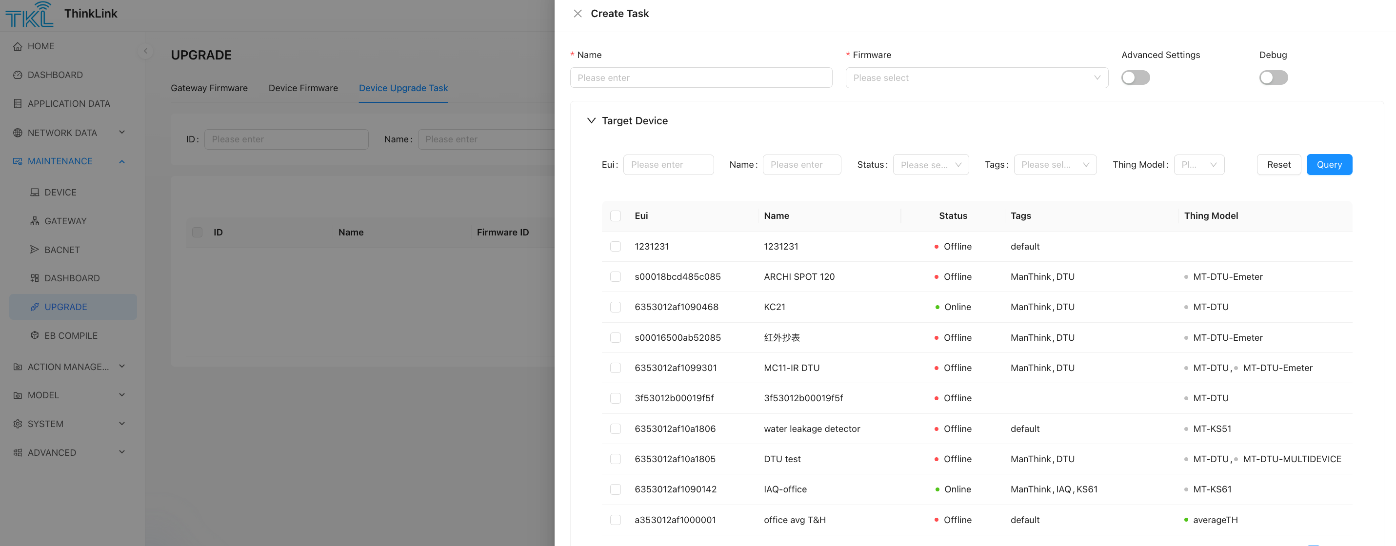
1.4.3 How to download firmware using ThinkLink
- Log in to the Thinklink platform: https://thinklink.manthink.cn/
- Go to the device management page and use the firmware upgrade function.
- Upload the
.obinfile, located in the release folder under the code folder.
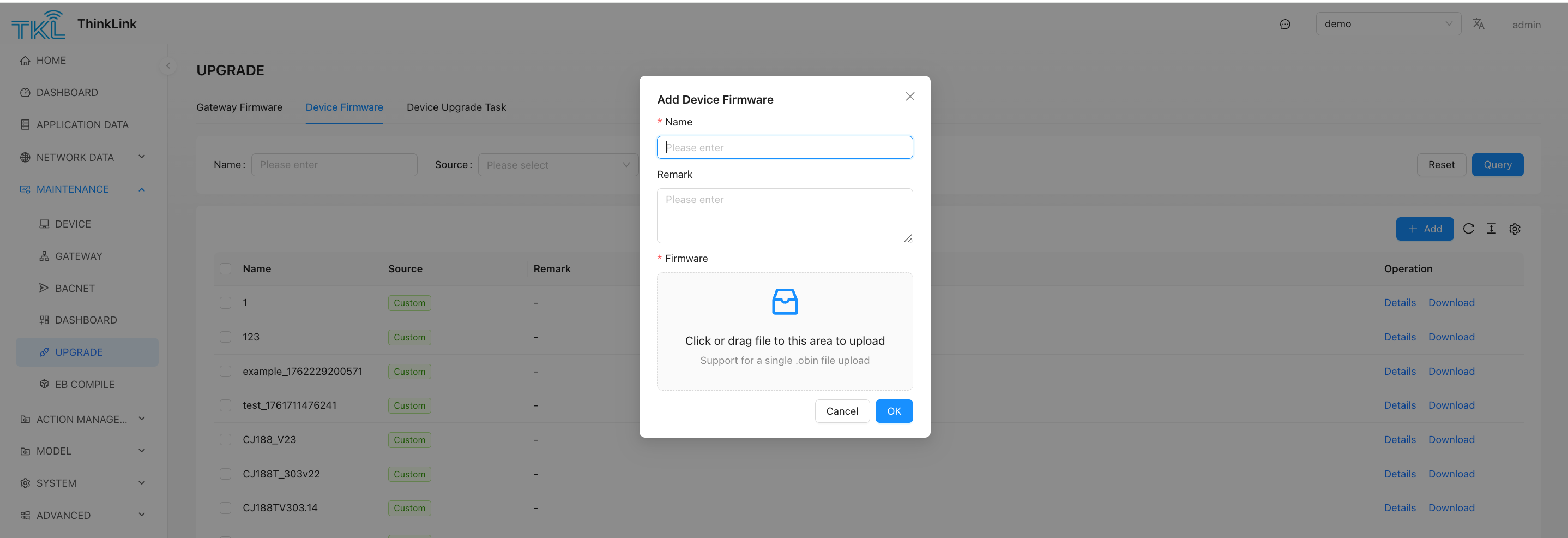
- Create an upgrade task and select the devices to be upgraded.
1.5 Code Configuration Instructions
In the entry file, the parameters need to be configured as shown in the following example:
let otaConfig = getOtaConfig({
    SwVersion: 31,
    BaudRate: 9600,
    StopBits: 1,
    DataBits: 8,
    Checkbit: CheckbitEnum.NONE,
    ConfirmDuty: 60,
    Battery: true,
    BzType: 101, // required ,2 bytes
    BzVersion: 2, // required,1 bytes
})
Configuration Precautions:
- SwVersion: The firmware version of the EB virtual machine, the current version is 31. The version must be consistent with the actual EB firmware, otherwise the upgrade will fail.
- BaudRate, StopBits, DataBits, Checkbit: These are the serial port configuration parameters for uart/RS-485. After the EB is upgraded, the configuration will be updated to the APP parameters. After the EB restarts, it will obtain the serial port configuration parameters from the APP parameters and configure the corresponding serial port. The configuration parameters should be consistent with the configuration of the sub-device that EB wants to read.
- ConfirmDuty: The duty cycle of the confirm package, the default is 60, which means that one confirm data package is sent every 60 packages.
- Battery Configuration
- For battery-powered devices, set to
true, and the module will run in Class A mode. - For non-battery-powered devices, set to
false, and the module will run in Class C mode.
- For battery-powered devices, set to
- BzType
The business type is used to identify different types of meters or businesses being read. It is a number type and is required. During the upgrade, EB will check the values of BzType and BzVersion. At least one of the two parameters must be different from the one in the upgrade package to be upgraded, otherwise EB will judge that the firmware has been upgraded.
- BzVersion
The business version number is used to identify different versions of firmware under the same business. It is a number type and is required. During the upgrade, EB will check the values of BzType and BzVersion. At least one of the two parameters must be different from the one in the upgrade package to be upgraded, otherwise EB will judge that the firmware has been upgraded.
- Advanced Parameters
For other advanced parameter configurations, please contact Manthink technical support.
2. System Buffer
2.1 Predefined System Buffers
The following 5 system buffers which can be used by EBModel for example :EBModel.APP
2.2 Buffer Function Description
| Buffer Name | Size | Permissions | Function Description |
|---|---|---|---|
| APP | 255 bytes | Read-only | Application data storage, can be modified via LoRa commands (such as 485 address, threshold, version number, etc.), users can utilize the space after 70. |
| APP_STATUS | 32 bytes | Read-only | System status information, including query timeout status, etc. |
| SENSOR_DATA | 128 bytes | Read-only | System built-in sensor data, collected periodically by the system |
| TEMPLATE | 128 bytes | Read/Write | Cache data that can be used by user code |
| DEVICE_STATUS | 16 bytes | Read-only | Device status data (battery level, LoRa field strength signal-to-noise ratio, etc.) |
2.3 Common Status Reading Examples
// Get query timeout status
const isQueryTimeOut = APP_STATUS.readUint8(2).bitwiseAnd(2).rightShift(1);

// Get battery voltage
const deviceBatteryVoltage = DEVICE_STATUS.readUint8(3);
3. Event-Specific Buffers
3.1 Query Event Buffer
- cmdBuffer: The instruction buffer sent to the sub-device, with a fixed length.
- ackBuffer: The buffer for receiving reply data from the sub-device, the length must be ≥ the actual reply data length.
3.2 Uplink Event Buffer
- txBuffer: The LoRa event sending buffer, consistent with the buffer sent by the event.
4. Buffer Operation Methods
Note 1: copy Rule (copy operation) and Cvt Rule (conversion operation) are two different format operations, and the returned objects are different and cannot be connected to each other.
Note 2: Each cvt rule supports connecting up to 6 operators, and each query event supports up to 15 cvt rules.
4.1 Data Copy Method
copy(sourceBuffer: Buffer, sourceOffset: number, byteLength: number, targetOffset: number)
sourceBuffer: The data source for the copy.
sourceOffset: The offset of the source data buffer.
byteLength: The byte length to read or write.
targetOffset: The offset of the target buffer.
Example:
copy(quEvent1.ackBuffer, 3, 72, 3)4.2 Integer Read/Write Methods
offset: The offset position of the calling buffer.
byteLength: The byte length to read or write.
value: The value to be written in a write operation.
Unsigned Integers
| Method | Byte Order | Width | Description |
|---|---|---|---|
readUintLE(offset, byteLength) | Little-endian | Dynamic | Read an unsigned integer |
writeUintLE(value, offset, byteLength) | Little-endian | Dynamic | Write an unsigned integer |
readUintBE(offset, byteLength) | Big-endian | Dynamic | Read an unsigned integer |
writeUintBE(value, offset, byteLength) | Big-endian | Dynamic | Write an unsigned integer |
readUint8(offset) | - | 8-bit | Read an unsigned 8-bit integer |
writeUint8(value, offset) | - | 8-bit | Write an unsigned 8-bit integer |
readUint16LE(offset) | Little-endian | 16-bit | Read an unsigned 16-bit integer |
writeUint16LE(value, offset) | Little-endian | 16-bit | Write an unsigned 16-bit integer |
readUint16BE(offset) | Big-endian | 16-bit | Read an unsigned 16-bit integer |
writeUint16BE(value, offset) | Big-endian | 16-bit | Write an unsigned 16-bit integer |
readUint32LE(offset) | Little-endian | 32-bit | Read an unsigned 32-bit integer |
writeUint32LE(value, offset) | Little-endian | 32-bit | Write an unsigned 32-bit integer |
readUint32BE(offset) | Big-endian | 32-bit | Read an unsigned 32-bit integer |
writeUint32BE(value, offset) | Big-endian | 32-bit | Write an unsigned 32-bit integer |
Signed Integers
The naming convention for methods is the same as for unsigned integers, just replace Uint with Int.
4.3 Floating-Point Read/Write Methods
offset: The offset position of the calling buffer.
value: The value to be written in a write operation.
| Method | Byte Order | Precision | Description |
|---|---|---|---|
readFloatLE(offset) | Little-endian | Single | Read a floating-point number |
writeFloatLE(value, offset) | Little-endian | Single | Write a floating-point number |
readFloatBE(offset) | Big-endian | Single | Read a floating-point number |
writeFloatBE(value, offset) | Big-endian | Single | Write a floating-point number |
readDoubleLE(offset) | Little-endian | Double | Read a double-precision floating-point number |
writeDoubleLE(value, offset) | Little-endian | Double | Write a double-precision floating-point number |
readDoubleBE(offset) | Big-endian | Double | Read a double-precision floating-point number |
writeDoubleBE(value, offset) | Big-endian | Double | Write a double-precision floating-point number |
4.4 String Read/Write Methods
offset: The offset position of the calling buffer.
length: The byte length to read or write.
value: The value to be written in a write operation.
| Method | Format | Description |
|---|---|---|
readAscii(offset, length) | ASCII | Read an ASCII string |
writeAscii(value, offset, length) | ASCII | Write an ASCII string |
readXaasc(offset, length) | XAASC | Read an XAASC format string |
writeXaasc(value, offset, length) | XAASC | Write an XAASC format string |
readXaf(offset, length) | XAF | Read an XAF format string |
writeXaf(value, offset, length) | XAF | Write an XAF format string |
4.5 Special Format Methods
offset: The offset position of the calling buffer.
length: The byte length to read or write.
value: The value to be written in a write operation.
| Method | Description |
|---|---|
readBcd(offset, length) | Read BCD code |
writeBcd(value, offset, length) | Write BCD code |
4.6 General Parameter Description
- offset: Buffer offset (starting from 0)
- length/byteLength: The byte length to be operated on
- value: The value to be written (CalcData type)
Return Value: All read and write methods return a CalcData or CopyData object, which can be used for subsequent calculations or assignment operations.
4.7 Calculation Operators
The EB SDK provides a rich set of calculation operation methods that support chained calls:
| Method | Description |
|---|---|
multiply | Multiplication operation |
divide | Division operation |
add | Addition operation |
minus | Subtraction operation |
bitwiseAnd | Bitwise AND operation |
bitwiseOr | Bitwise OR operation |
bitwiseXOR | Bitwise XOR operation |
power | Power operation |
not | Bitwise NOT |
leftShift | Left shift operation |
rightShift | Right shift operation |
round | Rounding operation |
ceil | Ceiling operation |
floor | Floor operation |
reverse | Reverse byte order |
| absolute | absolute value |
4.8 Example of Chained Calculation
// Read a 16-bit unsigned integer from ackBuffer, multiply by 10, and then write to txBuffer
quEvent1.pushEBData(upEvent1.txBuffer.writeUint16LE(quEvent1.ackBuffer.readUint16LE(2).multiply(10), 3));
5. Event
Events are categorized into the following three types:
● QueryEvent: Periodically sends commands to sub-devices to retrieve data.
● UpAfterQueryEvent: Triggered immediately after a query event completes, sending the processed data to the cloud.
● LoraUpEvent: Periodically transmits processed data to the cloud via LoRaWAN.
Below are the main methods and their functional descriptions:
5.1 pushEBData
● Function: Adds an operation (copy rule or cvt rule) to the event's action list. These operations will be executed when the event occurs.
● Usage: event.pushEBData(operation, options)
○ operation: The operation to be executed.
○ options: Optional parameters, which may include conditions.
Example:
quEvent1.pushEBData(quEvent1.cmdBuffer.copy(APP, 31, 1, 10), {
    condition: ExprCondition.PRE,
})
5.2 setPeriod
● Function: Sets the periodic execution interval for the event. This method takes a single parameter in seconds to define a fixed cycle.
● Usage: event.setPeriod(periodInSeconds)
○ periodInSeconds: The execution interval in seconds.
Example:
quEvent1.setPeriod(300);Note: If the event should be triggered by other events or actions rather than a fixed cycle, set the interval to a very long time (e.g., hours or days) to avoid interference from the fixed cycle.
5.3 setPeriodFromApp
● Function: Stores the event's execution interval value in a 4-byte space at the specified APP parameter address, using little-endian format. This allows dynamic adjustment of the event's execution cycle by modifying the APP parameter.
● Usage: quEvent1.setPeriodFromApp(appParameterAddress)
○ appParameterAddress: The APP parameter address specifying the 4-byte space to store the interval value (little-endian format).
Example:
quEvent1.setPeriodFromApp(70);6. Query Event
There are two types of query events: QueryEvent and UpAfterQueryEvent.
- QueryEvent: This is a regular query event. After the query is completed, the user performs operations related to
CopyRuleandCvtRulebased on the retrieved data. - UpAfterQueryEvent: This event is used for direct transparent transmission after the query. The user does not need to write additional
CvtRuleandCopyRulerelated operations.
6.1 Data Flow
The query event is executed according to the following process:
- Skip Query Check: If calling the Buffer value within the EB system, you can choose to skip the query command and go directly to step 11 to perform the copy operation.
- Prepare Command to Send: Generate a fixed-size command array.
- Data Copy (Copy Rule): Copy relevant bytes from other Buffers (if needed). The condition must be
ExprCondition.PRE. - Checksum Calculation: Calculate and place the checksum (if needed).
- Send Command: Send the command, retransmitting twice upon timeout.
- Wait for Reply: Wait for the sub-device to reply. If a timeout occurs, the current query ends.
- Receive Reply: Obtain the reply message.
- Checksum Verification: Check the checksum of the reply message (if needed).
- Data Validation: Check if the value at the specified position meets expectations.
- Data Uplink Check: If the event type is
UpAfterQueryEvent, the queried data is uploaded directly. The following actions are no longer executed. - Execute Copy Rule: Copy the reply data to the target Buffer according to the rule.
- Execute Conversion Rule (Cvt Rule): Perform calculation and conversion according to the rule and store the result. A
Copy Ruleis not allowed after a conversion rule. - Trigger Uplink: Decide whether to trigger data uplink based on the calculation result.
- End Event: Wait for the next event.
6.2 Whether to Execute the Query Action
If you do not want to execute the query action, you can call setIfSelect with the parameter IfSelectEnum.NO_QUERY to skip the query and data return processing.
quEvent1.setIfSelect(IfSelectEnum.NO_QUERY)6.3 Creating a Query Event
6.3.1 Example of Creating a Normal Query Event
let cmdBuffer1 = Buffer.from("0F 04 10 0A 00 24 D5 FD".replaceAll(" ", ""), "hex");
let ackBuffer1 = Buffer.alloc(77);
let quEvent1 = new QueryEvent("quEvent1", {
    cmdBuffer: cmdBuffer1,
    ackBuffer: ackBuffer1,
}).setPeriod(300);
6.3.2 Example of Creating an UpAfterQueryEvent
let cmdBuffer1 = Buffer.from("0F 04 10 0A 00 24 D5 FD".replaceAll(" ", ""), "hex");
let ackBuffer1 = Buffer.alloc(77);
let quEvent1 = new UpAfterQueryEvent("quEvent1", {
    cmdBuffer: cmdBuffer1,
    ackBuffer: ackBuffer1,
}).setPeriod(300);
6.4 Update Data Operation
The following example copies 1 byte from the 31st byte of the APP parameter to the 10th byte of cmdBuffer before executing the query operation.
quEvent1.pushEBData(quEvent1.cmdBuffer.copy(APP,31,1,10),{
      condition: ExprCondition.PRE,
  }
)
6.5 Setting the Query Checksum
quEvent1.setQueryCrc({
    Mode: CrcMode.CRC16,
    placeIndex: 6,
    LittleEndian: true,
    crcCheckRange: {
        startIndex: 0,
        endIndex: cmdBuffer1.length - 3
    }
});
6.6 Setting the Reply Checksum
quEvent1.setAckCrc({
    Mode: CrcMode.CRC16,
    placeIndex: 6,
    LittleEndian: true,
    crcCheckRange: {
        startIndex: 0,
        endIndex: ackBuffer1.length - 3
    }
});
6.7 Adding a Reply Check Rule
quEvent1.addAckCheckRule(0, 0x10); // Check if the 0th byte is 0x106.8 Executing Data Copy or Calculation Rules
// Bind read/write/copy operation
quEvent1.pushEBData(upEvent1.txBuffer.copy(quEvent1.ackBuffer,3,72,3),
  {
    condition: ExprCondition.ONTIME
  });
quEvent1.pushEBData(upEvent1.txBuffer.writeUint8(isQueryTimeOut, 1));

// Note 1: Every operation in a query event must execute a copy action, and then a cvt action. No copy operation is allowed after a cvt operation.
// Note 2: Each cvt rule supports a maximum of 6 connected actions, and each query event supports a maximum of 15 cvt rules.

// If a data uplink needs to be triggered after executing CvtRule, the ActAfterCvt parameter needs to be added to the event.
// ActionAfertExpr.NO: Default, no action is taken.
// ActionAfertExpr.ALWAYS: Triggers data upload regardless of the result.
// ActionAfertExpr.UP_TO_RESULT: Depends on the result of the Cvt operation. Upload is triggered when the operation result is greater than 0, otherwise not.
6.9 setupCov
setupCov is a method encapsulated by the EB compiler to implement the COV (Change of Value) function. In many scenarios, EB needs to frequently read device data and then compare the read data with the last uploaded data. When the difference is greater than the set threshold, data upload is performed. This mechanism can significantly reduce the power consumption of data transmission, reduce platform-side junk data, and minimize the occupation of air resources while ensuring data real-time performance.
setupCov will occupy space in SENSORDATA corresponding to the size of the value. For example, when binaryDataType is Uint16LE, it occupies 2 bytes of SENSORDATA space. After setupCov is executed, it returns the index value in SENSORDATA, which is used by the uplink event to copy data from SENSORDATA. When the COV condition is met, a packet of data uplink will be triggered. In the uplink event, the sensor value in SENSORDATA is copied to txBuffer and then sent, completing the data upload.
ackBufferIndex: The position to read data from in the ackBuffer from sub device.up.event: The uplink event instance.up.txBufferIndex: The address where the sampled value is stored in the uplink data.binaryDataType: The byte type of the data being operated on.appBufferCovThresholdIndex: The address in the APP buffer where the COV threshold is stored.txCovResultIndex: The address in the uplink buffer where the COV status is stored. This value is meaningless and needs to be reserved intxBuffer.
Return Value: The index stored in SENSORDATA.
Usage Example:
let sIndex=quEvent1.setupCov({
  ackBufferIndex: 0, // The position to read data from in the acknowledgment message
  up: {
    event: upEvent1, // The uplink event instance
    txBufferIndex: 2 // The address where the sampled value is stored in the uplink data
  },
  binaryDataType: "Uint16LE", // The byte type of the data being operated on
  appBufferCovThresholdIndex: 5, // The address in the APP buffer where the COV threshold is stored
  txCovResultIndex: 3 // The address in the uplink buffer where the COV status is stored
});
7. Uplink Event (LoraUp Event)
7.1 Data Flow
The uplink event is executed according to the following process:
- Execute Copy Operation: Execute the copy operation according to the rules (if needed).
- Execute Calculation Operation: Execute the calculation operation according to the rules (if needed).
- Send LoRa Data: Send data in the predetermined format.
7.2 Creating an Uplink Event
let txBuffer1 = Buffer.alloc(20);
txBuffer1[0] = 0x01; // Data identifier

let upEvent1 = new LoraUpEvent("upEvent1", {
    txBuffer: txBuffer1,
    txPort: 12
}).setPeriod(300);
7.3 Data Processing (Copy and Convert)
upEvent1.pushEBData(upEvent1.txBuffer.copy(TEMPLATE, 3, 4, 3), {
    condition: ExprCondition.ONTIME
});
upEvent1.pushEBData(
    upEvent1.txBuffer.writeUint8(isQueryTimeOut, 1), {
        condition: ExprCondition.ONTIME,
        Repeat: 0,
        ActAfterCvt: ActionAfertExpr.NONE
    }
);
8. Checksum and Configuration
8.1 CRC16 Mode
quEvent1.setQueryCrc({
    Mode: CrcMode.CRC16,
    Poly: "a001", // Optional, default is 0xa001, Modbus uses a001
    placeIndex: -2, // Checksum position, positive for forward, negative for reverse
    LittleEndian: true, // Byte order, default is true, Modbus uses LittleEndian
    crcCheckRange: {
        startIndex: 0, // Calculation start position
        endIndex: cmdBuffer1.length - 3 // Calculation length
    }
});
8.2 CCITT16 Mode
quEvent1.setQueryCrc({
    Mode: CrcMode.CCITT16,
    Poly: "1021", // Optional, default is "1021"
    placeIndex: -2,
    LittleEndian: true,
    crcCheckRange: {
        startIndex: 0,
        endIndex: cmdBuffer1.length - 3
    }
});
8.3 SUM Mode
quEvent1.setQueryCrc({
    Mode: CrcMode.SUM,
    CrcLen: 6, // Calculate the sum of 6 bytes
    placeIndex: -2,
    LittleEndian: true,
    crcCheckRange: {
        startIndex: 0,
        endIndex: cmdBuffer1.length - 3
    }
});
9. Operation Conditions (Condition)
9.1 Copy Operation Conditions
| Condition | Description |
|---|---|
ExprCondition.NONE | Always execute the copy operation |
ExprCondition.ONTIME | Execute the copy operation when the sub-device replies correctly |
ExprCondition.TIMEOUT | Execute the copy operation when the query operation times out |
| ExprCondition.PRE | Copy data from other buffers before querying |
9.2 Read/Write Operation Conditions
| Condition | Description |
|---|---|
ExprCondition.NONE | Always execute the calculation operation |
ExprCondition.ONTIME | Execute the calculation operation when the sub-device replies correctly |
ExprCondition.TIMEOUT | Execute the calculation operation when the query operation times out |
9.3 Action After Conversion (ActAfterCvt)
To start this trigger action, the last call must be to the txBuffer of the uplink event.
| Action | Description |
|---|---|
ActionAfertExpr.NONE | No action after calculation |
ActionAfertExpr.ALWAYS | Always trigger uplink regardless of the result |
ActionAfertExpr.UP_TO_RESULT | Trigger uplink when the result is greater than 0 |
ActionAfertExpr.ALWAYS_REBOOT | Reboot the device after the calculation is complete |
9.4 Repeat Conversion (Repeat)
- Default value: 1
- Purpose: Used for the loop operation of the CvtRule of the uplink event. If the condition parameter
Repeatis 3, the same conversion operation will be executed three times. After each operation, the source address of the data will be increased by the length of the operated data as the source address for the next operation; the destination address will be increased by the length of the target result data as the target address for the next operation. The following is an example.
// For a calc action, the loop operation count is implemented with the following result:
// The second parameter of writeUintLE is the loop step.
quEvent1.pushEBData(upEvent1.txBuffer.writeUintLE(quEvent1.ackBuffer.readBcd(2,7),3,7), {Repeat: 3})
This is equivalent to the following three operations:
// is equivalent to:

// Iteration 1: Read from position 2
quEvent1.pushEBData(upEvent1.txBuffer.writeUintLE(quEvent1.ackBuffer.readBcd(2,7),3,7));
// Iteration 2: Read from position 9 (2 + 7)
quEvent1.pushEBData(upEvent1.txBuffer.writeUintLE(quEvent1.ackBuffer.readBcd(9,7),10,7));
// Iteration 3: Read from position 16 (9 + 7)
quEvent1.pushEBData(upEvent1.txBuffer.writeUintLE(quEvent1.ackBuffer.readBcd(16,7),17,7));
10. Built-in Encapsulated Functions
The EB compiler provides some built-in common methods for users to call. In addition, users can also encapsulate their own commonly used methods into plug-ins and add them to the EB compiler, so that they can be called more conveniently to achieve the required functions.
11. Example Code
Please contact Manthink for example code.
The user code is located under the project folder. Users can create multiple folders according to their own projects, and each folder can have an EB file.
import {Buffer} from "buffer";
import {buildOtaFile} from "@EBSDK/run";
import {
    ActionAfertExpr,
    CrcMode,
    EBBuffer,
    EBModel,
    ExprCondition,
    LoraUpEvent,
    QueryEvent
} from "@EBSDK/EBCompiler/all_variable";
import {CheckbitEnum, getOtaConfig, HwTypeEnum, UpgrdTypeEnum} from "@EBSDK/otaConfig";

let otaConfig = getOtaConfig({
    BaudRate: 9600,
    StopBits: 1,
    DataBits: 8,
    Checkbit: CheckbitEnum.NONE,
    Battery: true,
    ConfirmDuty: 60,
    BzType: 101, // required ,2 bytes
    BzVersion: 2, // required,1 bytes
    SwVersion: 31
})
const MODBUS_TT = (ebModel: EBModel) => {
    // the Buffer which will be transmitted to sub device by UART/RS-485/M-Bus
    let cmdBuffer1=Buffer.from("12345678b1b2b3b4b5b6b7b8b9".replaceAll(" ", ""), "hex")
    // The expected message from the child device does not need to fully match the content, but its length should be greater than the actual reply.
    let ackBuffer1= Buffer.from("a1a2a3a4a5a6a7a8a9".replaceAll(" ",""),"hex")
    //build a query event with cmdBuffer1 and ackBuffer1, every 300 seconds, the cmdBuffer1 will be transmitted  and expecting ackBuffer1
    let quEvent1=new QueryEvent("quEvent1", {
        cmdBuffer: cmdBuffer1,
        ackBuffer: ackBuffer1,
        MulDev_NewGrpStart: true
    }).setPeriod(300)
    // EB will cacu the CRC before transmit cmdBuffer1
    quEvent1.setQueryCrc({
        Mode: CrcMode.SUM,
        CrcLen:1,
        placeIndex:-2,
        LittleEndian:true,
        crcCheckRange:{
            startIndex:0,
            endIndex:-2
        }
    })
    // when sub-device reply the message , EB start to find the first bytes which should be 0x68
    quEvent1.addAckCheckRule(0,0xa1)
    //the last byte of ackBuffer1 should be 0xa9
    quEvent1.addAckCheckRule(ackBuffer1.length-1,0xa9)
    //EB check the CRC of ackBuffer1
   /*
    quEvent1.setAckCrc({
        Mode: CrcMode.SUM,
        CrcLen:1,
        placeIndex:-2,
        LittleEndian:true,
        crcCheckRange:{
            startIndex:0,
            endIndex:-2
        }
    })
    */
    // build a upEvent1 which will transmit txBuffer by LoRaWAN and the period will be 1 year
    // EB also can make a condition to trigger the transmition when act a convertion
    let upEvent1= new LoraUpEvent("upEvent1", {
        txBuffer:Buffer.from("c1c2c3c4c5c6c7c8c9c0d1d2d3d4d5d6d7d8d9".replaceAll(" ",""),"hex"),
        txPort: 12
    }).setPeriod(86400*365)
    // read 2 bytes value with little-endian int16 format from ackBuffer of quEvent1 and then write to txBuffer with little-endian when quEvent1's ack event happen
    // ONTIME of condition means the message is replied , also the action can be TIMEOUT
    quEvent1.pushEBData(upEvent1.txBuffer.writeInt16LE(
        quEvent1.ackBuffer.readInt16LE(2), 3),{
        condition: ExprCondition.ONTIME
    })
    // a copy action from ackBuffer of quEvent1
    quEvent1.pushEBData(upEvent1.txBuffer.copy(quEvent1.ackBuffer,5,4,6),
        {
            condition: ExprCondition.ONTIME,
        }
    )
    //copy bytes from APP ,this byte is battery voltage
    quEvent1.pushEBData(upEvent1.txBuffer.copy(EBModel.APP,31,1,10),
        {
            condition: ExprCondition.ONTIME,
        }
    )
    // a read-write action ,ActionAfertExpr.ALWAYS means that the action will trigger a tranmition by LoRaWAN
    quEvent1.pushEBData(upEvent1.txBuffer.writeUint16LE(
        quEvent1.ackBuffer.readUint16LE(11), 2),{
        condition: ExprCondition.ONTIME,
        ActAfterCvt:ActionAfertExpr.UP_TO_RESULT
    })
    // ----------------------------------------------------
    return JSON.stringify(ebModel, null, 2)
}
buildOtaFile(__filename, otaConfig, MODBUS_TT)
11.1 Output File Description
After executing the script, four files will be generated in the release folder under the project directory. For example, if the project name is test and its path is project/test, the following four files will be created in project/test/release:
- test.bin: Original compiled binary file
- test.json: Compilation process file
- test.obin: Final upgrade package file (for device firmware updates)
- test.ota: OTA upgrade descriptor file
Among these, .bin, .json, and .ota are intermediate files, while test.obin is the final file used for upgrades.
11.2 Serial Port Configuration
In the entry file, configure the serial port parameters as shown in the example below:
let otaConfig = getOtaConfig({
    SwVersion: 31,
    BaudRate: 9600,
    StopBits: 1,
    DataBits: 8,
    Checkbit: CheckbitEnum.NONE,
    ConfirmDuty: 60,
    Battery: true,
    BzType: 101,  // Required (2 bytes)
    BzVersion: 2, // Required (1 byte)
})
Configuration Notes:
- Battery Setting
- Set to
truefor battery-powered devices (module operates in Class A mode). - Set to
falsefor non-battery-powered devices (module operates in Class C mode).
- Set to
- Advanced Parameters
For additional advanced configurations, contact Manthink Technical Support.
11.3 Query Events (QueryEvent)
The device periodically sends queries via UART or RS-485 and expects responses of a specified length. Upon receiving data, the sub-device replies via RS-485 or UART, and EB processes the response based on predefined rules.
let cmdBuffer1 = Buffer.from("0F 04 10 0A 00 24 D5 FD".replaceAll(" ", ""), "hex");
let ackBuffer1 = Buffer.alloc(77);
let quEvent1 = new QueryEvent("quEvent1", {
    cmdBuffer: cmdBuffer1,
    ackBuffer: ackBuffer1,
}).setPeriod(300);- QueryEvent defines Modbus query logic, including command transmission, response reception, and data validation.
- cmdBuffer: Modbus command frame sent to the device (constructed per the device protocol manual).
- ackBuffer: Buffer for receiving response data (size must match expected response length).
11.4 CRC Checksum for Outgoing Commands
- CRC checksum ensures Modbus communication reliability. Configure the correct CRC mode per device protocol.
- placeIndex: Position of CRC checksum in the data frame.
- LittleEndian: Whether to use little-endian byte order (must match device settings).
quEvent1.setQueryCrc({
    Mode: CrcMode.CRC16,
    placeIndex: 6,
    LittleEndian: true,
    crcCheckRange: {
        startIndex: 0,
        endIndex: cmdBuffer1.length - 3
    }
});
11.5 CRC Validation for Received Data
- CRC validation is a critical step to ensure the reliability of Modbus communication. It is essential to configure the correct CRC mode according to the device protocol.
**placeIndex**** indicates the position of the CRC verification value in the data frame.****LittleEndian**** specifies whether to use little-endian order for CRC calculation, which must match the device configuration.**
quEvent1.setAckCrc({
  Mode: CrcMode.CRC16,
  placeIndex: 6,
  LittleEndian: true,
  crcCheckRange: {
    startIndex: 0,
    endIndex: ackBuffer1.length - 3
  }
})
11.6 Response Data Format Validation
quEvent1.addAckCheckRule(0, cmdBuffer1[0]) // Verify if the replied 485 address is correct
quEvent1.addAckCheckRule(1, cmdBuffer1[1]) // Verify the function code
quEvent1.addAckCheckRule(2, ackBuffer1.length - 5) // Verify the data length
11.7 Packing Upstream Data
Any data from the buffer can be copied into the upstream message. In this example, the UART and 485 read-timeout flags are placed into the upstream data.
quEvent1.pushEBData(upEvent1.txBuffer.writeUint8(isQueryTimeOut, 1))
quEvent1.pushEBData(upEvent1.txBuffer.copyFrom({
  bufferOffset: 3,
  byteLength: 72,
  buffer: quEvent1.ackBuffer
}, 3), {
  condition: ExprCondition.ONTIME
})